Exploit Development: Investigating Kernel Mode Shadow Stacks on Windows
Introduction
A little while ago I presented a talk at SANS HackFest 2024 in California. My talk provided a brief “blurb”, if you will, about a few of the hypervisor-provided security features on Windows - specifically surrounding the mitigations instrumented through Virtualization-Based Security (VBS). Additionally, about one year ago I noticed that “Kernel-mode Hardware-enforced Stack Protection” was a feature available in the UI of the Windows Security Center (before this, enabling this feature had to be done through an undocumented registry key). This UI toggle is actually a user-friendly name for the Intel CET Shadow-Stack feature for kernel-mode stacks.
Intel CET technically refers to multiple features, including both Indirect Branch Tracking (IBT) and Shadow-Stack. Windows does not implement IBT (and instead leverages the existing Control Flow Guard feature). Because of this, any references to Intel CET in this blog post really refer specifically to the shadow stack feature.
Since this feature can finally be enabled in a documented manner (plus the fact that there was not a whole lot of information online as to how Windows actually implements kernel-mode CET) I thought it would be worth including in my talk at SANS HackFest.
At the time when I was preparing my slides for my presentation I didn’t get to spend a lot of time (due to the scope of the talk which included multiple mitigations plus a bit about hypervisor internals) on all of the nitty-gritty details of the feature. Most of this came down to the fact that this would require some reverse engineering of the Secure Kernel. To-date, doing dynamic analysis in the Secure Kernel is not only undocumented and unsupported but it is also fairly difficult (at least to a guy like me it is!).
However, as Divine Providence would have it, right after my talk my friend Alan Sguigna sent me a copy of the SourcePoint debugger - which is capable of debugging the Secure Kernel (and much more!) Given that KCET (kernel-mode Intel CET) was already top-of-mind for me, as I had just given a talk which included it, I thought it would be a good opportunity to blog about something I love - exploit mitigations and Windows internals! This blog post will be divided into two main parts:
- “The NT (
ntoskrnl.exe) perspective” (e.g., examining how NT kicks-off the creation of a kernel-mode shadow stack) - “The Secure Kernel perspective” (e.g., we then will showcase how (and why) NT relies on the Secure Kernel to properly facilitate kernel-mode shadow stacks by actively debugging the Secure Kernel with SourcePoint!)
The “internals” in this blog post will not surround those things which my good friends Alex and Yarden blogged about here (such as showcasing additions to the instruction set, changes in CPU specs, etc.). What I hope to touch on in this blog post is (to the best of my abilities, I hope!) the details surrounding the Windows-specific implementation of Intel CET in kernel-mode, changes made in order to support shadow stacks, my reverse engineering process, nuances surrounding different situations in the stack creation code paths, and (what I think is most interesting) how NT relies on Secure Kernel in order to maintain the integrity of kernel-mode shadow stacks.
I (although I know I am not worthy of it) am asked from time to time my methodology in regards to reverse engineering. I thought this would be a good opportunity to showcase some of this for the 1-2 people who actually care! As always - I am not an expert and I am just talking about things I find interesting related to exploitation and Windows internals. Any comments, corrections, and suggestions are always welcome :). Let’s begin!
tl;dr CET, Threads, and Stacks
To spend only a brief moment on the main subject of this blog post - Intel CET contains a feature known as the Shadow-Stack. This feature is responsible for mitigating ROP-based attacks. ROP allows an attacker (which has control of a stack associated with a thread which is/will executing/execute) to forge a series of return addresses which were not originally found during the course of execution. Since a ret will load the stack pointer into the instruction pointer, and given an attacker can control the contents of the stack - this allows an attacker to therefore control the contents of the instruction pointer by re-using existing code found within an application (our series of forged return addresses found within the .text section or other location of executable code). The reason why attackers commonly use ROP is because memory corruption (generally speaking) results in the corruption of memory. Corrupting memory infers you can write to said memory - but with the advent of Data Execution Prevention (DEP) and Arbitrary Code Guard (ACG), regions of memory which are writable (like the stack) are not executable. This means attackers need to re-use existing code found within an application instead of directly writing their own shellcode like the “old” days. The Shadow-Stack feature works by maintaining a protected “shadow stack” which contains an immutable copy of what the stack should look like based on normal execution. Anytime a ret instruction happens, a comparison is made between the “traditional” stack (which an attacker can control) and the shadow stack (which an attacker cannot control because it is protected by hardware or a higher security boundary). If the return address (the address which contains the ret instruction) of the traditional stack doesn’t match the shadow stack, we can infer someone corrupted the stack, which would be indicative potentially of a ROP-based attack. Since stack corruption could lead to code execution - CET enforces that the process should die or the system crashes (in the case of KCET).
With this basic understanding, I first want to delve into one nuance most people are probably familiar with, but maybe not every reader is. As you probably learned in Computer Science 101 - threads are responsible for executing code. During the course of execution, a particular thread will have a need to store information it may need in the short term (variables, function parameters and also return addresses). A thread will store this information on the stack. There is a dedicated region of memory associated with “the stacks” and each thread is afforded a slice of that region resulting in a per-thread stack. All this to say, when we refer to the “stack” we are, in fact, referring to a “per-thread stack”.
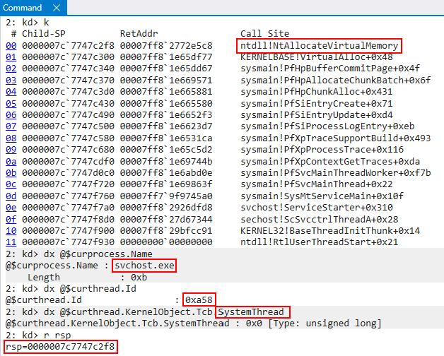
Given that we are talking about kernel-mode Intel CET in this blog post - our minds will immediately jump to thinking about the protection of kernel-mode stacks. Since user-mode threads have user-mode stacks, it is only logical that kernel-mode threads have kernel-mode stacks - and this is very true! However, the main thing I want hearken on is the fact that kernel-mode stacks are NOT limited to kernel-mode threads. User-mode threads also have an associated kernel-mode stack. The implementation of threads on Windows sees user-mode threads as having two stacks. A user-mode stack and a kernel-mode stack. This is because user-mode threads may spend time actually executing code in kernel-mode. A good example of this is a system call. A system call is typically issued in context of the particular thread which issued it. A system call will cause the CPU to undergo a transition to start executing code at a CPL of 0 (kernel-mode). If a user-mode thread invokes a system call, and a system call requires execution of kernel-mode code - it would be a gaping security flaw to have kernel-mode storing kernel-mode information on a user-mode stack (which an attacker could just read). We can see below svchost.exe is about to make a system call, and execution is in user-mode (ntdll!NtAllocateVirtualMemory).
After the syscall instruction within ntdll!NtAllocateVirtualMemory is executed, execution transitions to the kernel. If we look at the image below, when execution comes to the kernel we can see this is the exact same thread/process/etc. which was previously executing in user-mode, but RSP (the stack pointer) now contains a kernel-mode address.
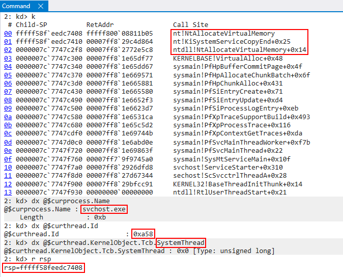
This may seem very basic to some - but my point here is for the understanding of the unfamiliar reader. While kernel-mode Intel CET is certainly a kernel-mode exploitation mitigation, it is not specific to only system threads since user-mode threads will have an associated kernel-mode stack. These associated kernel stacks will be protected by KCET when the feature is enabled. This is to clear up confusion later when we see scenarios where user-mode threads are receiving KCET protection.
Thread and Stack Creation (NT)
There are various scenarios and conditions in which thread stacks are created, and some of these scenarios requires a bit more “special” handling (such as stacks for DPCs, per-processor ISR stacks, etc.). What I would like to focus on specifically in this blog post is walking through how the KCET shadow stack creation works for the kernel-mode stack associated with a new user-mode thread. The process for a normal system thread is relatively similar.
As a given thread is being created, this results in the kernel-managed KTHREAD object being allocated and initialized. Our analysis begins in nt!PspAllocateThread, right after the thread object itself is created (nt!ObCreateObjectEx with a nt!PsThreadType object type) but not yet fully initialized. The kernel-mode stack is not yet configured. The configuration of the kernel stack happens as part of the thread initialization logic in nt!KeInitThread, which is invoked by nt!PspAllocateThread. Note that initThreadArgs is not a documented structure, and I reverse engineered the arguments to the best of my ability.
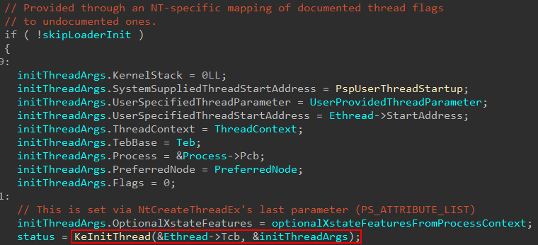
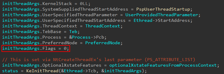
In the above image, we can see for the call to nt!KeInitThread the system-supplied thread start address is set to nt!PspUserThreadStart. This will perform more initialization of the thread. Depending on the type of thread being created, this function (and applicable parameters) can change. As an example, a system thread would call into nt!PspSystemThreadStartup and a secure thread into nt!PspSecureThreadStartup (something beyond the scope of this blog but maybe I will talk about in a future post if I have time!). Take note as well of the first parameter to nt!KeInitThread, which is Ethread->Tcb. If you are not familiar, the first several bytes of memory in an ETHREAD object are actually the corresponding KTHREAD object. This KTHREAD object can be accessed by the Tcb member of an ETHREAD object. The KTHREAD object is the kernel’s version of the thread, the ETHREAD object is the executive’s version.
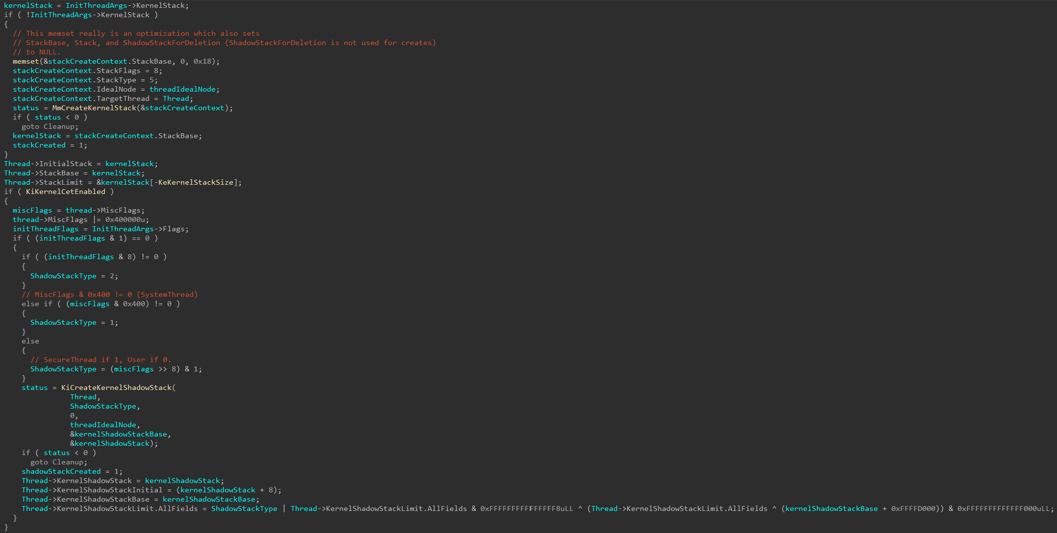
Moving on, once execution reaches nt!KeInitThread, one of the first things which occurs in the initialization of the thread is the thread’s kernel stack (even though we are dealing with a user-mode thread). This is done through a call to nt!MmCreateKernelStack. This function is configurable to create multiple types of stacks in kernel-mode. We will not investigate this first blatant call to nt!MmCreateKernelStack, but instead shift our focus to how the call to nt!KiCreateKernelShadowStack is made, as we can see below, as this obviously is where the shadow stack “fun” will come (and will also make a call to nt!MmCreateKernelStack!). As a point of contention, the arguments passed to nt!MmCreateKernelStack (which are not relevant in this specific case respective to shadow stack creation) are undocumented and I have reverse engineered them as best I can here.
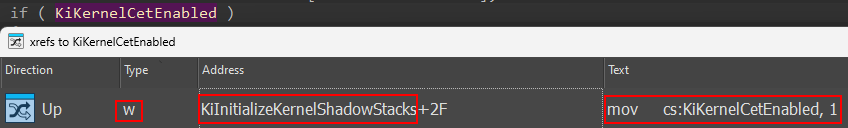
We can see, obviously, that the code path which leads towards nt!KiCreateKernelShadowStack is gated by nt!KiKernelCetEnabled. Looking at cross-references to this global variable, we can see that it is set as part of the call to nt!KiInitializeKernelShadowStacks (and this function is called by nt!KiSystemStartup).
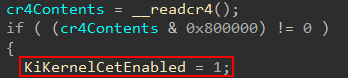
Looking at the actual write operation, we can see this occurs after extracting the contents of the CR4 control register. Specifically, if the 23rd bit (0x800000) of the CR4 register is set this means that the current CPU supports CET. This is the first “gate”, so to speak, required. We will see later it is not the only one at the end of this first section of the blog on NT’s role in kernel-mode shadow stack creation.
If CET is supported, the target thread for which a shadow stack will be created for (as a point of contention, in other scenarios not described here in this blog post an empty thread can be supplied to nt!KiCreateKernelShadowStack) has the 22nd bit (0x400000) set of the Thread->MiscFlags bitmask. This bit corresponds to Thread->MiscFlags.CetKernelShadowStack - which makes sense! Although, as we mentioned, we are dealing with a user-mode thread this is the creation of its kernel-mode stack (and, therefore, kernel-mode shadow stack).
We can then see, based on the value of either MiscFlags or what I am calling “thread initialization flags” one of the arguments passed to nt!KiCreateKernelShadowStack (specifically ShadowStackType) is configured.
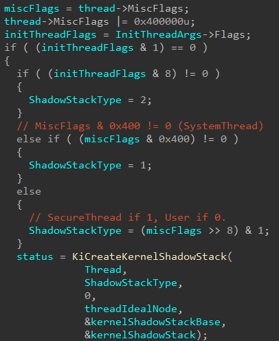
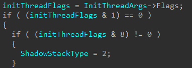
The last two code paths depend on how Thread->MiscFlags is configured. The first check is to see if Thread->MiscFlags has the 10th (0x400) bit set. This corresponds to Thread->MiscFlags.SystemThread. So what happens here is that the shadow stack type is defined as a value of 1 if the thread for which we are creating a kernel-mode shadow stack for is a system thread.
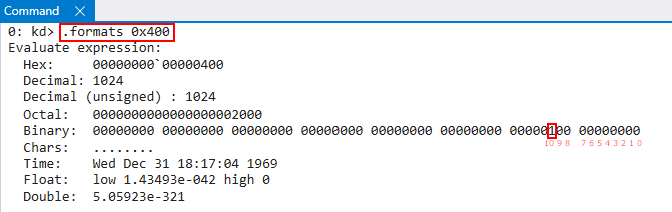
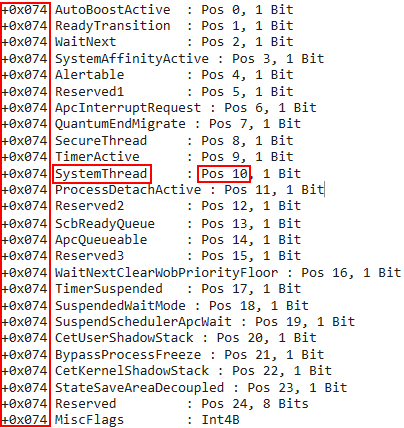
For the reader which is unfamiliar and curious how I determined which bit in the bitmask corresponds to which value, here is an example. As we know,
0x400was used in the bitwise AND operation. If we look at0x400in binary, we can see it corresponds to bit 10.
If we then use
dt nt!_KTHREADin WinDbg, we can seeMiscFlags, at bit10(starting at an offset from0) corresponds toMiscFlags.SystemThread. This methodology is true for future flags and also for how we determinedMiscFlags.CetKernelShadowStackearlier.
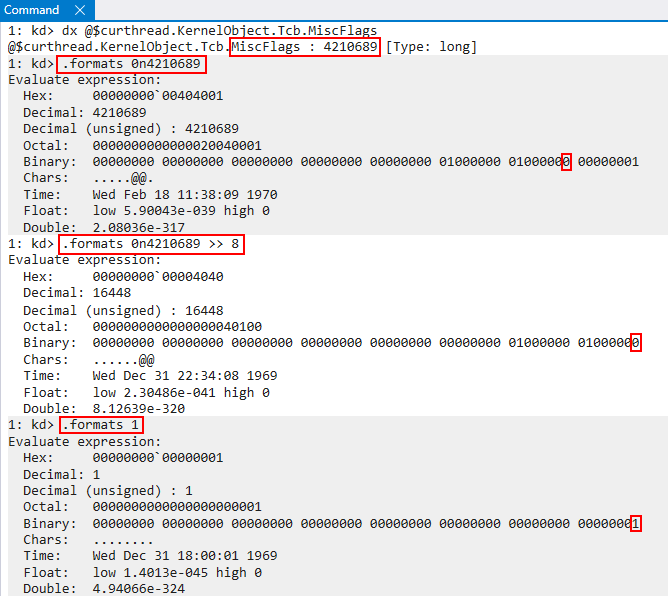
Continuing on, the next path that can be taken is based on the following statement: ShadowStackType = (miscFlags >> 8) & 1;. What this actually does is it shifts all of the bits in the mask to “the right” by 8 bits. The desired effect here is that the 8th bit (from an offset of 0) is moved to the first (0th) position. Since 1, in decimal, is 00000001 in binary - this allows the 8th bit (from an offset of 0) to be bitwise “AND’d” 1. In other words, this checks if the 8th bit (from an offset of 0) is set.
If we look at the raw disassembly of nt!KeInitThread we can see exactly where this happens. To validate this, we can set a breakpoint on the bitwise AND operation. We then can “mimic” the AND operation, and tell WinDbg to break if r14d after performing a bitwise AND with 1 is non-zero. If the breakpoint is reached this would indicate to us the target thread should be that of a “secure thread”.
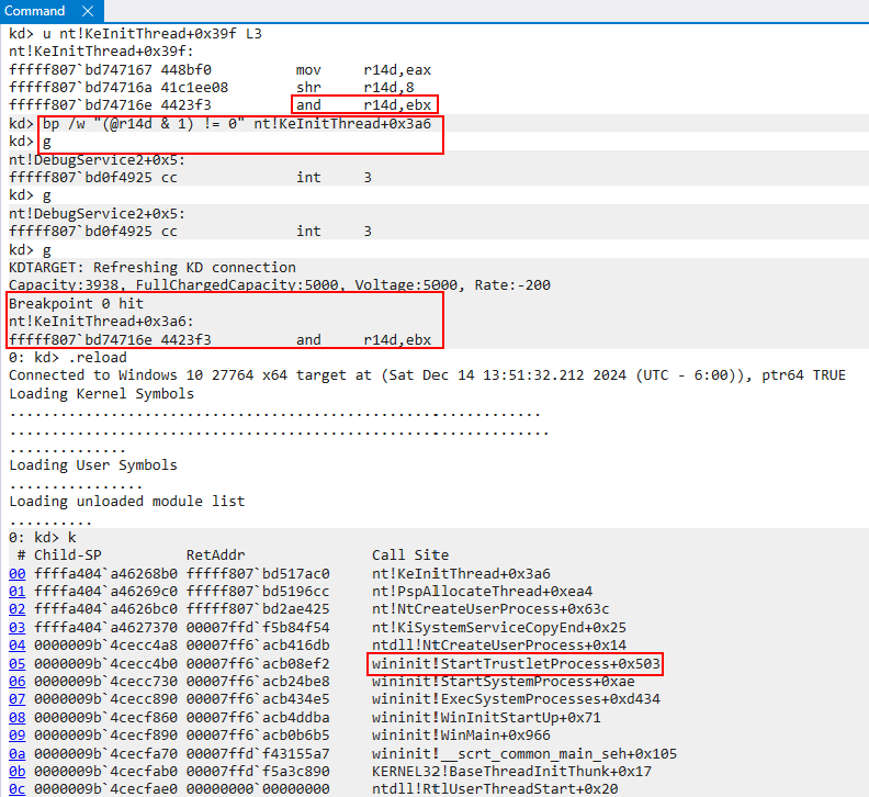
We can see after we have hit the breakpoint we are in a code path which calls wininit!StartTrustletProcess. I will not go too far into detail, as I tend to sometimes on unrelated subjects, but a trustlet (as referred to by Windows Internals, Part 1, 7th Edition) refers to a “secure process”. We can think of these as special protected processes which run in VTL 1.
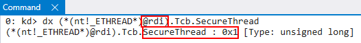
At the time the breakpoint is reached, the target thread of the operation is in the RDI register. If we examine this thread, we can see that it resides in LsaIso.exe - which is a “secure process”, or a trustlet, associated with Credential Guard.
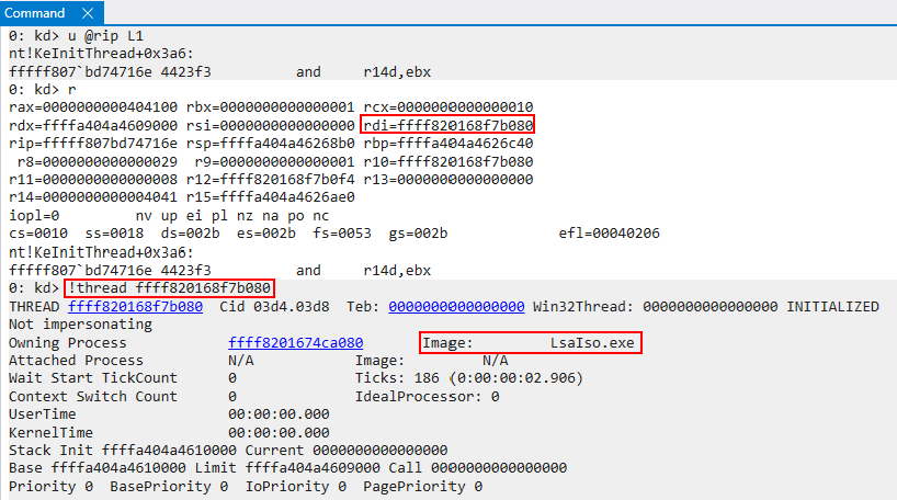
More specifically, if we examine the SecureThread member of the thread object, we can clearly see this is a secure thread! Although we are not going to examine the “flow” of a secure thread, this is to validate the code paths taken which we mentioned earlier.
After (yet another) side track - the other code path which can be taken here is that SecureThread is 0 - meaning ShadowStackType is also 0. A value of 0 I am just referring to as a “normal user-mode thread”, since there is no other special value to denote. For our purposes, the stack type will always be 0 for our specific code path of a user-mode thread having a kernel-mode shadow stack created.
This means the only other way (in this specific code path which calls nt!KiCreateKernelShadowStack from nt!KeInitThread) to set a non-zero value for ShadowStackType is to have (initThreadFlags & 8) != 0.
Now, if we recall how nt!KeInitThread was invoked for a user-mode thread, we can see that Flags is always explicitly set to 0. For our purposes, I will just denote that these flags come from other callers of nt!KeInitThread, specifically early threads like the kernel’s initial thread.
nt!KeInitThread will then eventually invoke nt!KiCreateKernelShadowStack. As you recall what I mentioned earlier, nt!MmCreateKernelStack is a “generic” function - capable of creating multiple kinds of stacks. It should be no surprise then that nt!KiCreateKernelShadowStack is just a wrapper for nt!MmCreateKernelStack (which uses an undocumented structure as an argument which I have reversed here as I can). It is also worth noting that nt!KiCreateKernelShadowStack is always called with the stack flags (third parameter) set to 0 in the user-mode thread code path via nt!KeInitThread.
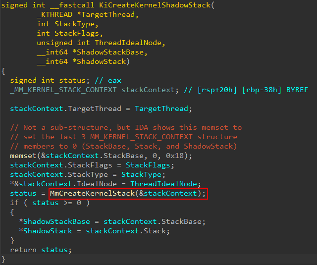
Given nt!MmCreateKernelStack’s flexibility to service stack creations for multiple types, it makes sense that the logic for creation of the shadow stack is contained here. In fact, we can see on a successful call (an NTSTATUS code greater than 0, or 0, indicates success) the shadow stack information is stored.
When execution reaches nt!MmCreateKernelStack (for the shadow stack creation) there are effectively two code paths which can be taken. One is to use an already “cached” stack, which is a free cached stack entry that can be re-purposed for the new stack. The other is to actually allocate and create a new shadow stack.
The first thing that is done in nt!MmCreateKernelStack is the arguments from the call are copied and stored - additionally allocateShadowStackArgs are initialized to 0. This is an undocumented structure I, to the best of my ability, reverse engineered and can possibly be used in a call to nt!MiAllocateKernelStackPages if we hit the “new stack allocation” code path instead of the “cached stack” code path. Additionally, a specific “partition” is selected to be the “target partition” for the operation.
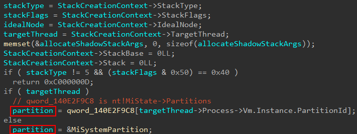
Firstly you may be wondering - where does nt!MiSystemPartition come from, or the term partition in general? This global is of type nt!_MI_PARTITION and, according to Windows Internals, Part 1, 7th Edition, “consists of [the memory partition’s] own memory-related management structures, such as page lists, commit charge, working set, page trimmer, etc.”. We can think of these partitions as a container for memory-management related structures for things, as an example, like a Docker container (the concept is similar to how virtualization is used to isolate memory, with each VM having its own set of page tables). I am not an expert on these partitions, and they do not appear (at least to me) very documented, so please read the applicable portion of Windows Internals, Part 1, 7th Edition I just mentioned.
The system partition always exists, which is this global variable. This system partition represents the system. It is also possible for partition to be associated with a target process - and this is exactly what nt!MmCreateKernelStack does.
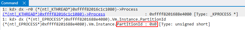
We then can see from the previous image that the presence of a target thread is used to help determine the target partition (recall earlier I said there were some “special” cases where no thread is provided, which we won’t talk about in this blog). If a target thread is present, we extract a “partition ID” from the process housing the target thread for which we wish to create a shadow stack. An array of all known partitions is managed by the global variable nt!MiState which stores a lot of the commonly-accessed information, such as system memory ranges, pool ranges, etc. For our target thread’s process, there is no partition associated with it. This means the index of 0 is provided, which is the index of the system default partition. This is how the function knows where to index the known cached shadow stack entries in the scenarios where the cache path is hit.
The next code path(s) that are taken revolve around the type of stack operation occurring. If we can recall from earlier, nt!MmCreateKernelStack accepts a StackType argument from the input structure. Our “intermediary” ShadowStackType value from the call in nt!KiCreateKernelShadowStack supplies the StackType value. When StackType is 5, this refers to a “normal” non-shadow stack operation (such as the creation of a new thread stack or the expansion of a current one). Since 5 for a StackType is reserved for “normal” stacks, we know that callers of nt!MmCreateKernelStack provide a different value to specify “edge” cases (such as a “type” of kernel shadow stack). In our case, this will be set to 0.
In conjunction with the stack type, a set of “stack flags” (StackFlags) provide more context about the current stack operation. An example of this is to denote whether or not the stack operation is the result of a new thread stack or the expansion of an existing one. Since we are interested specifically in shadow stack operations, we will skip over the “normal” stack operations. Additionally, for the kernel-mode shadow stack path for a user-mode thread, StackFlags will be set to 0.
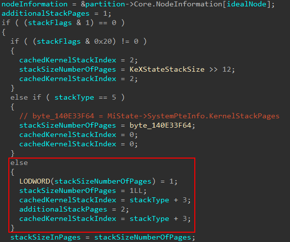
The next thing nt!MmCreateKernelStack will do is to determine the size of the stack. The first bit of the stack flag bitmask denotes if a non-regular (larger) stack size is needed. If it isn’t needed, some information is gathered. Specifically in the case of kernel-mode shadow stacks we will hit the else path. Note here, as well, a variable named cachedKernelStackIndex is captured. Effectively this variable will be set to 3, as stackType is empty, in the case of a kernel-mode shadow stack operation for a user-mode thread. This will come into play later.
At this point I noticed that there has been a change to KPRCB that I couldn’t find other information on the internet about, so I thought it would be worth documenting here since we need to talk about the “cached stack” path anyways! In certain situations a cached stack entry can be retrieved from the current processor (KPRCB) servicing the stack creation. The change I noticed comes in the fact that KPRCB now has two cached stack regions (tracked by Prcb->CachedStacks[2]). The old structure member was Prcb->CachedStack, which has been around since Windows 10 1709.
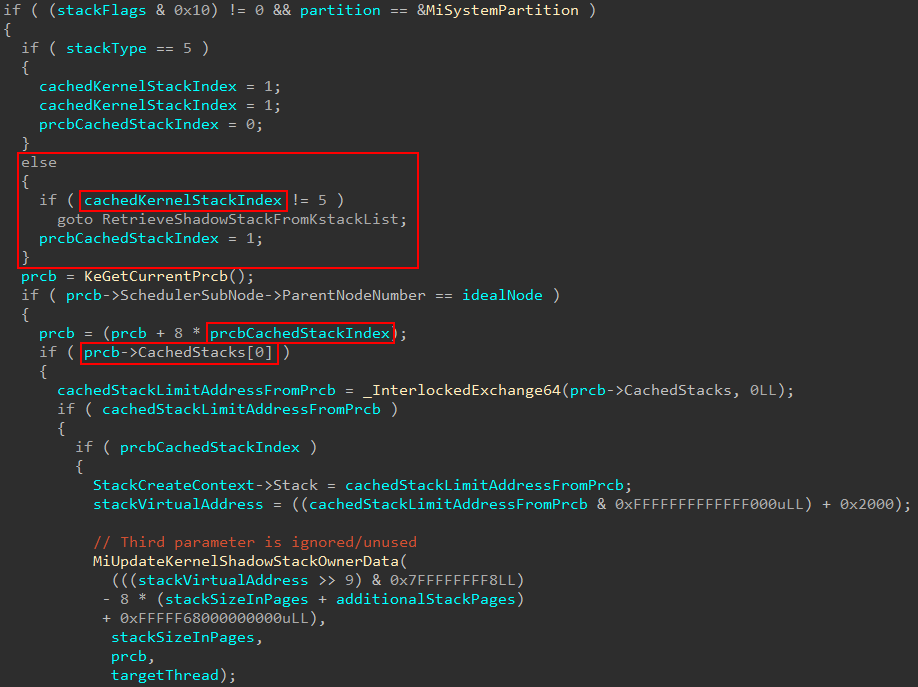
In the above case we can see when StackType is 5, the CachedStacks[] index is set to 0. Otherwise, it is 1 (tracked by the variable prcbCachedStackIndex in decompiler).
Note that
cachedKernelStackIndexis highlighted but is not of importance to us yet.
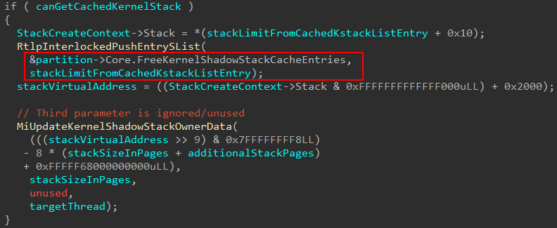
This infers this new CachedStacks[] index is specifically for shadow stacks to be cached! Note that in the above screenshot we see nt!MiUpdateKernelShadowStackOwnerData. This check is gated by checking if prcbCachedStackIndex is set to 1, which is for shadow stacks. When a cached entry for a stack is found the “owner data” gets updated. What this really does is take the PFNs associated with shadow stack pages and associates them with the target shadow stack.
There is actually a second way, in addition to using the PRCB’s cache, to use a free and unused shadow stack for a caller requesting a new shadow stack. This second way, which I will show shortly, also will use nt!MiUpdateShadowStackOwner, and relies on cachedKernelStackIndex.
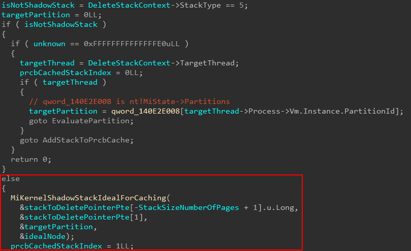
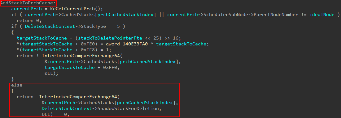
How does the PRCB cache get populated? When a stack is no longer needed nt!MmDeleteKernelStack is called. This function can call into nt!MiAddKernelStackToPrcbCache, which is responsible for re-populating both lists managed by Prcb->CachedStacks[2]. nt!MmDeleteKernelStack works almost identically as nt!MmCreateKernelStack - except the result is a deletion. They both even accept the same argument type - which is a structure providing information about stack to be either created or deleted. Specifically for shadow stack scenarios, there is a member of this structure which I have named ShadowStackForDeletion which is only used in nt!MmDeleteKernelStack scenarios. If it is possible, the deleted stack is stored in Prcb->CachedStacks[] at the appropriate index - which in our case is the second (1 from 0th index) since the second is for shadow stacks.
For various reasons, including the fact that there is no free cached stack entry to use from the PRCB, a caller who is requesting a new shadow stack may not receive a cached stack through the current processor’s PRCB. In cases where it is possible to retrieve a cached stack, a caller may receive it through the target partition’s FreeKernelShadowStackCacheEntries list. A processor grouping is known as a node on a NUMA (Non-uniform memory architecture) system which many modern systems run on. Windows will store particular information about a given node in the nt!_MI_NODE_INFORMATION structure. There is an array of these structures manageed by the partition object.

Each node, in addition to the processor’s KPRCB, has a list of free cached stacks for use!
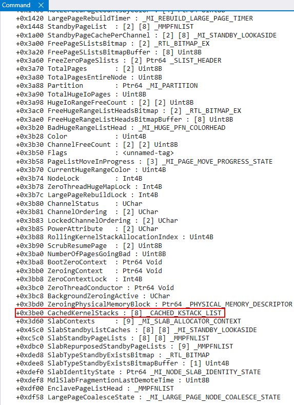
This CachedKernelStacks member of the node information structure is an array of 8 nt!_CACHED_KSTACK_LIST structures.
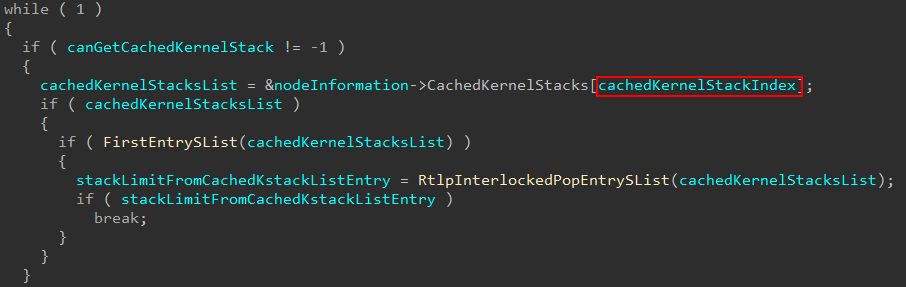
As we mentioned earlier, the variable cachedKernelStackIndex captured towards the beginning of the nt!MmCreateKernelStack function denotes, in the event of this cached stack path being hit, which list to grab an entry from. Each list contains a singly-linked list of free entries for usage. In the event an entry is found, the shadow stack information is also updated as we saw earlier.
At this point execution would be returned to the caller of nt!MmCreateKernelStack. However, it is also possible to have a new stack created - and that is where the “juice” is, so to speak. The reason why all of these stack cache entries can be so trivially reused is because their security/integrity was properly configured, once, through the full “new” path.
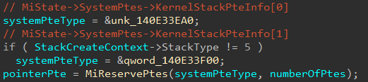
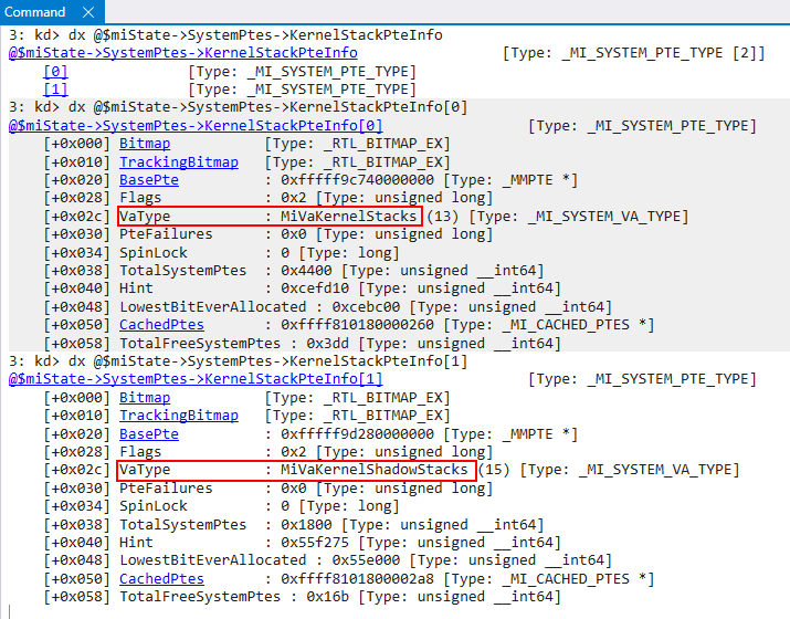
For the “new” stack path (for both shadow and non-shadow, although we will focus on shadow stacks) PTEs are first reserved for the stack pages via nt!MiReservePtes. Using the global nt!MiState, the specific system PTE region for the PTE reservation is fetched. Since there can be two types of stacks (non-shadow and shadow) there are now two system PTE regions for kernel-mode stacks. Any stack type not equal to 5 is a shadow stack. The corresponding system VA types are MiVaKernelStacks and MiVaKernelShadowStacks.
After the reservation of the PTEs (shadow stack PTEs in our case) nt!MmCreateKernelStack is effectively done with its job. The function will call into nt!MiAllocateKernelStackPages, which will effectively map the memory reserved by the PTEs. This function accepts one parameter - a structure similar to nt!MmCreateKernelStack which I have called _ALLOCATE_KERNEL_STACK_ARGS. If this function is successful, the StackCreateContext->Stack member of our reverse-engineered nt!MmCreateKernelStack argument will be filled with the address of the target stack. In our case, this is the address of the shadow stack.

nt!MiAllocateKernelStackPages will do some standard things, which are uninteresting for our purposes. However, in the case of a shadow stack operation - a call to nt!VslAllocateKernelShadowStack occurs. A couple of things happen leading up to this call.
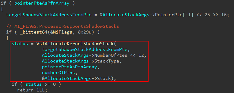
As part of the call to nt!MiAllocateKernelStackPages, nt!MmCreateKernelStack will prepare the arguments, and stores an empty pointer I have named “PFN array”. This PFN array does not hold nt!_MMPFN structures, but instead quite literally holds the raw/physical PFN value from the “pointer PTE” associated with the target shadow stack address. A pointer PTE essentially means it is a pointer to a set of PTEs that map to a given memory region. This pointer PTE came from the previous call to nt!MiReservePtes in nt!MmCreateKernelStack from the shadow stack VA region. This “PFN array” holds the actual PFN from this pointer PTE. The reason it is called a “PFN array” is because, according to my reverse engineering, it is possible to store multiple values (although I always noticed only one PFN being stored). The reason for this is because nt!VslAllocateKernelShadowStack will call into the Secure Kernel. Because of this, the Secure Kernel can just take the raw PFN and multiply it by the size of a page to calculate the physical address of the pointer PTE. The pointer PTE is important because it points to all of the PTEs reserved for the target shadow stack.
We can also see that this call is gated by the presence of the nt!_MI_FLAGS bit ProcessorSupportsShadowStacks. ProcessorSupportsShadowStacks gets set as a result of initializing the “boot” shadow stacks (like ISR-specific shadow stacks, etc.) The setting of this bit is gated by nt!KiKernelCetEnabled, which we have already seen earlier (nt!KiInitializeKernelShadowStacks).

We only briefly touched on it earlier, but we said that nt!KiKernelCetEnabled is set if the corresponding bit in the CR4 register for CET support is set. This is only partly true. Additionally, LoaderParameterBlock->Extension.KernelCetEnabled must be set, where LoaderParameterBlock is of type LOADER_PARAMETER_BLOCK. Why is this important to us?
nt!VslAllocateKernelShadowStack, which we just mentioned a few moments ago, will actually result in a call into the Secure Kernel. This is because nt!VslAllocateKernelShadowStack, similar to what was shown in a previous post of mine, will result in a secure system call.
This means that VBS must be running. This means that it is logical to assume that if nt!KiKernelCetEnabled is set, and if MiFlags.ProcessorSupportsShadowStacks is set, the system must know that VBS (more specifically HVCI in our case) is running because if these flags are set, a secure system call will be issued - which infers the Secure Kernel is present. Since as part of the boot process the LOADER_PARAMETER_BLOCK arrives to us from winload.exe, we can go directly to winload.exe in IDA to see how LoaderParameterBlock->Extension.KernelCetEnabled is set.
Easily-locatable is the function winload!OslSetVsmPolicy in winload.exe. In this function there is a call to winload!OslGetEffectiveHvciConfiguration. This function “returns” multiple values by way of output-style parameters. One of these values is a boolean which denotes if HVCI is enabled. The way it is determined if HVCI is enabled is via the registry key HKLM\SYSTEM\CurrentControlSet\Control\DeviceGuard\Scenarios\HypervisorEnforcedCodeIntegrity since the registry is already available to Windows at this point in the boot process. It also will read present CI policies as well, which are capable of enabling HVCI apparently. If HVCI is enabled, only then does the system go to check the kernel CET policy (winload!OslGetEffectiveKernelShadowStacksConfiguration). This will also read from the registry (HKLM\SYSTEM\CurrentControlSet\Control\DeviceGuard\Scenarios\KernelShadowStacks) where one can denote if “audit-mode”, which results in an ETW event being generated on kernel CET being violated, or “full” mode where a system crash will ensue.

The reason why I have belabored this point is to outline that kernel CET REQUIRES that HVCI be enabled on Windows! We will see specifically why in the next section.
Moving on, this call to nt!VslAllocateKernelShadowStack will result in a secure system call. Note that _SHADOW_STACK_SECURE_CALL_ARGS is not a public type and is just a “custom” local type I created in IDA based on reverse engineering.
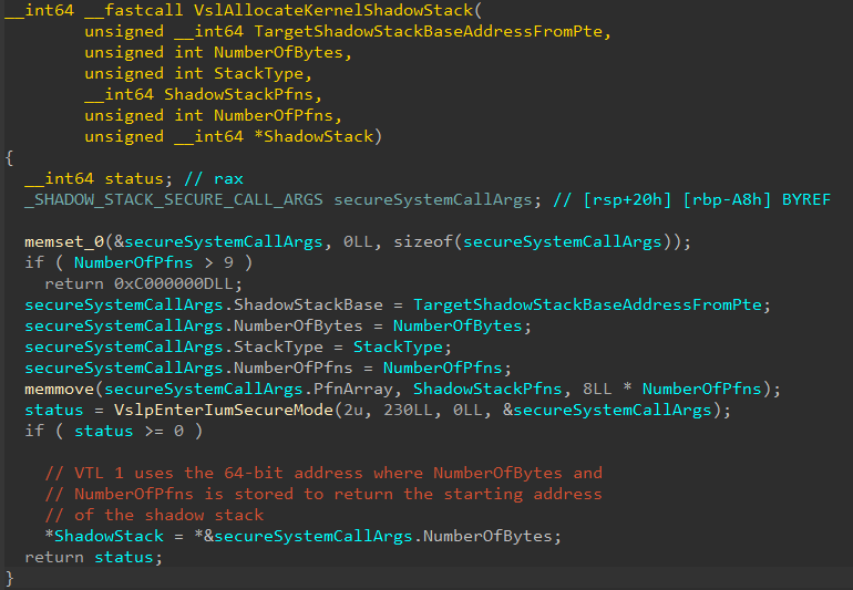
We can now see the arguments that will be passed to VTL 1/Secure Kernel. This is the end the shadow stack creation in VTL 0! Execution now will take over with VTL 1.
Debugging the Secure Kernel with SourcePoint
SourcePoint for Intel is a new piece of software that works in conjunction with a specific board (in this case the AAEON UP Xtreme i11 Tiger Lake board) which is capable of “debugging the undebuggable”. SourcePoint (which is what I am using as a term synonymous with “the debugger”) achieves this by leveraging the JTAG technology via the Intel Direct Connect Interface, or DCI. I won’t belabor this blog post by including an entire writeup on setting up SourcePoint. Please follow this link to my GitHub wiki where I have instructions on this.
Shadow Stack Creation (Secure Kernel)
With the ability to dynamically analyze the Secure Kernel, we can turn our attention to this endeavor. Since I have previously shown the basics surrounding secure system calls in my last post, I won’t spend a lot of time here. Where we will pick up is in securekernel.exe in the secure system call dispatch function securekernel!IumInvokeSecureService. Specifically on the version of Windows I am using, a secure system call number (SSCN) of 230 results in a shadow stack creation operation.
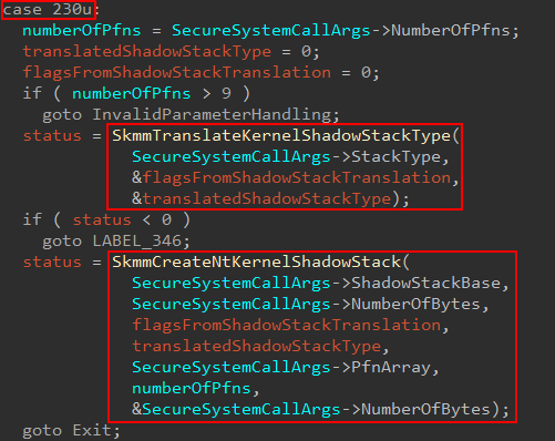
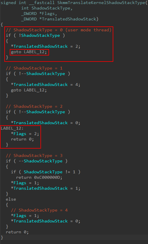
The first thing that will be done is to take the shadow stack type provided from NT and “convert it” to a “Secure Kernel specific” version via securekernel!SkmmTranslateKernelShadowStackType. In our case (a user-mode thread’s kernel-mode shadow stack) the Flags return value is 2, while the translated shadow stack type is also 2.
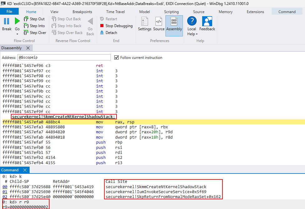
In SourcePoint, we simply set a breakpoint on securekernel!SkmmCreateNtKernelShadowStack. We can see for this operation, the “translated shadow stack” is 2, which is for a user-mode thread receiving a kernel-mode shadow stack.
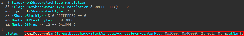
The first thing that securekernel!SkmmCreateNtKernelShadowStack does is to validate the presence of several pre-requisite items, such as the presence of KCET on the current machine, and if the shadow stack type is valid, etc. If these conditions are true, securekernel!SkmiReserveNar will be called which will reserve a NAR, or Normal Address Range.
A Normal Address Range, according to Windows Internals, 7th Edition, Part 2 “[represents] VTL 0 kernel virtual address ranges”. The presence of a NAR allows the Secure Kernel to be “aware” of a particular VTL 0 virtual address range of interest. NARs are created for various regions of memory, such as shadow stacks (like in our case), the kernel CFG bitmap pages, and other regions of memory which require the services/protection of VTL 1. This most commonly includes the region of memory associated with a loaded image (driver).
The present NARs are stored in what is known as a “sparse” table. This sort of table (used for NARs and many more data types in the Secure Kernel, as mentioned in my previous blog) contain many entries, with only the used entries being mapped. However, I noticed in my reversing and debugging this didn’t seem to be the case in some circumstances. After reaching out to my friend Andrea Allievi, I finally understood why! Only driver NARs are stored in a sparse table (which is why in my last blog post on some basic Secure Kernel image validation we saw a driver being loaded used the sparse table). In the case of these “one-off”, also known as “static” NARs (used for the CFG bitmap, shadow stacks, etc.), the NARs are not stored in a sparse table - they are instead stored in an AVL tree - tracked through the symbol securekernel!SkmiNarTree. This tree tracks multiple types of static NARs. In addition to this, there is a shadow stack specific list tracked via securekernel!SkmiShadowStackNarList.
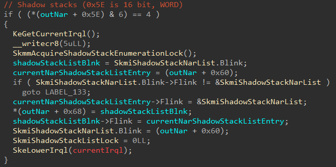
As part of the NAR-creation logic, the current in-scope NAR (related to the target shadow stack region being created) is added to the list to be tracked of NARs related to shadow stacks (it is also added, as mentioned, to the “static” NAR list via the AVL tree root securekernel!SkmiNarTree)
As a side note, please take heed that it is not my intent to reverse the entire NAR structure for the purposes of this blog post. The main things to be aware about are that NARs let VTL 1 track memory of interest in VTL 0, and that NARs contain information such as the base region of memory to track, number of pages in the region, the associated secure image object (if applicable), and other such items.
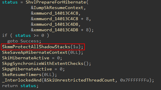
One of the main reasons for tracking NARs related to shadow stacks in its own unique list is due to the fact there are a few scenarios where work needs to be completed against all shadow stacks. This includes integrity checks of shadow stack performed by Secure Kernel Patch Guard (SKPG) and also when the computer is going through hibernation.
Moving on, after the NAR creation you will notice several calls to securekernel!SkmiGetPteTrace. This functionality is used to maintain the state of transitions of various memory targets like NTEs, PTEs and PFNs. I learned this after talking, again, to Andrea, who let me know why I was always seeing these calls fail. The reason these calls are not relevant to us (and why they don’t succeed, thus gating additional code) is because logging every single transition would be very expensive and it is not of great importance. Because of this there are only certain circumstances where logging takes place. In the example below securekernel!SkmiGetPteTrace would trace the transition of the NTEs associated with the shadow stack (as the NTEs are configured part of the functionality of reserving the NAR.) An NTE, for the unfamiliar reader, is called a “Normal Table Entry” and there is one NTE associated with every “page of interest” that the Secure Kernel wants to protect in VTL 0 (notice how I did not say every page in VTL 0 has an associated NTE in VTL 1). NTEs are stored and indexed through a global array, just like PTEs historically have been in NT.
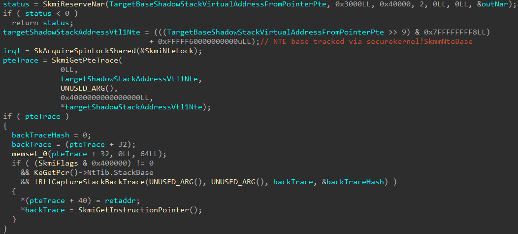
Note, as well that KeGetPrc() call in the above screenshot is wrong. This is because, although KeGetPrc() simply just grab whatever is in [gs:0x8]. However, just as both the kernel and user-mode make use of GS for their own purposes, Secure Kernel does the same. The “PRC” data in Secure Kernel is in its own format (the same with thread objects and process objects). This is why IDA does not know how to deal with it.
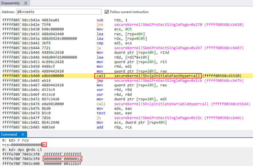
After the NAR (and NTEs are tracked), and skipping over the aforementioned logging mechanism, a loop in invoked which calls securekernel!SkmiClaimPhysicalPage. There are two parameters leveraged here, the physical frame which corresponds to the original pointer PTE provided as one of the original secure system call arguments and a bitmask, presumably a set of flags to denote the type of operation.
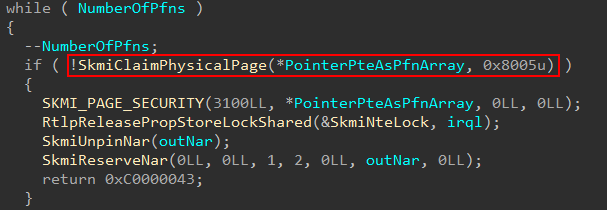
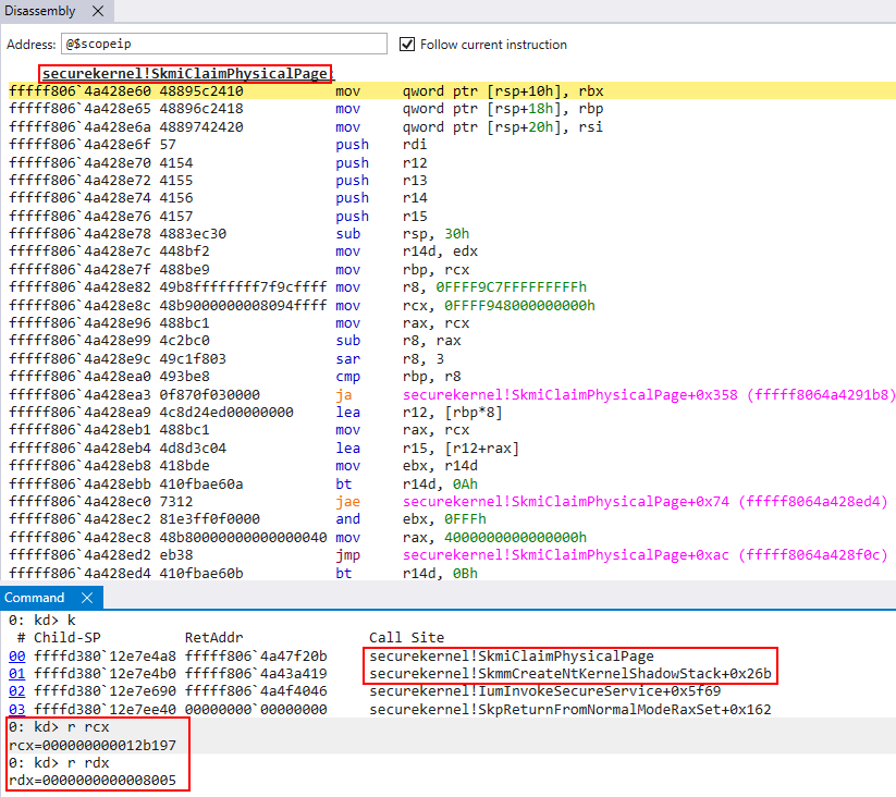
This loop will iterate over the number of PTEs related to the shadow stack region, calling into securekernel!SkmiClaimPhysicalPage. This function will allow the Secure Kernel to own these physical pages. This is achieved primarily by calling securekernel!SkmiProtectPageRange within securekernel!SkmiClaimPhysicalPage, setting the pages to read-only in VTL 0, and thus allowing us later down the road to map them into the virtual address space of the Secure Kernel.
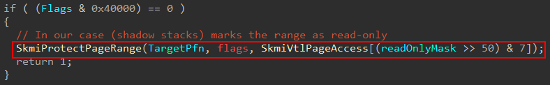
Now you will see that I have commented on this call this will mark the pages as read-only. How did I validate this? The call to securekernel!SkmiProtectPageRange will, under the hood, emit a hypercall (vmcall) with a hypercall code of 12 (decimal). As I mentioned before in a post about HVCI that the call code of 12, or 0xC in hex, corresponds to the HvCallModifyVtlProtectionMask hypercall, according to the TLFS (Hypervisor Top Level Functional Specification). This hypercall is capable of requesting that a given guest page’s protection mask is modified. If we inspect the arguments of the hypercall, using SourcePoint, we can get a clearer picture of what this call does.
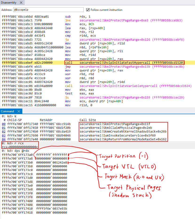
- Bytes 0-8 (8 bytes) are the target partition.
-1denotes “self” (#define HV_PARTITION_ID_SELF ((HV_PARTITION_ID) -1)). This is because we are dealing with the root partition (see previously-mentioned the post on HVCI for more information on partitions) - Bytes 8-12 (4 bytes) denote the target mask to set. In this case we have a mask of
9, which corresponds toHV_MAP_GPA_READABLE | HV_MAP_GPA_USER_EXECUTABLE. (This really just means marking the page as read-only, I talked with Andrea as to whyHV_MAP_GPA_USER_EXECUTABLEis present and it is an un-related compatibility problem). - Bytes 12-13 (1 bytes) specify the target VTL (in this case VTL 0)
- Bytes 13-16 (3 bytes) are reserved
- Bytes 16-N (N bytes) denote the target physical pages to apply the permissions to. In this case, it is the physical address of the shadow stack in VTL 0. Remember, physical are identity-mapped. The physical addresses of memory are the same in the eyes of VTL 1 and VTL 0, they just have a different set of permissions applied to them depending on which VTL the processor is currently executing in.
This prevents modification from VTL 0 and allows the Secure Kernel to now safely map the memory and initialize it as it sees fit. The way this is mapped into the Secure Kernel is through the region of memory known as the hyperspace. A PTE from the hyperspace region is reserved and the contents are filled with the appropriate control bits and the PFN of the target shadow stack region.
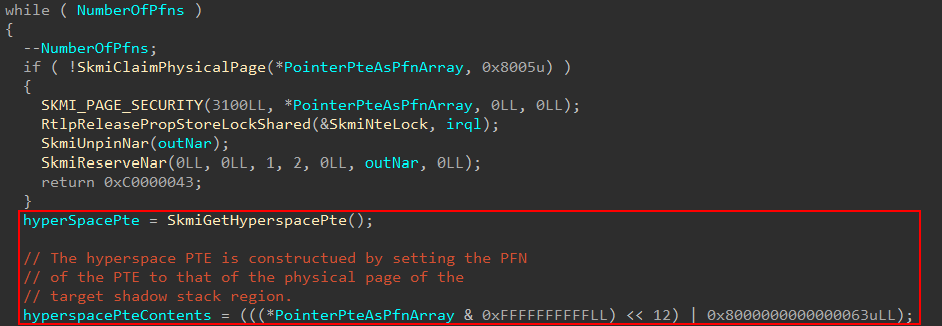
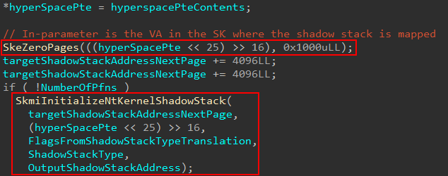
Hyperspace is a region of memory, denoted by Windows Internals 7th Edition, Part 1, where memory can be temporarily mapped into system space. In this case, it is temporarily mapped into the Secure Kernel virtual address space in order to initialize the shadow stack with the necessary information (and then this mapping can be removed after the changes are committed, meaning the physical memory itself will be configured still). After the shadow stack region is mapped the memory is zeroed-out and securekernel!SkmiInitializeNtKernelShadowStack is called to initialize the shadow stack.
The main emphasis of this function is to properly initialize the shadow stack based on the type of shadow stack. If you read the Intel CET Specs on supervisor (kernel) shadow stacks, something of interest stands out.
For a given shadow stack, at offset 0xFF8 (what we will refer to as the “bottom” of the shadow stack and, yes I am aware the stack grows towards the lower addresses!), something known as the “supervisor shadow stack token” is present. A token (as we will refer to it) is used to verify a shadow stack, and also provides metadata such as if the current stack is busy (being actively used on a processor, for example). The token is important, as mentioned, because it is used to validate a supervisor shadow stack is an actual valid shadow stack in kernel mode.
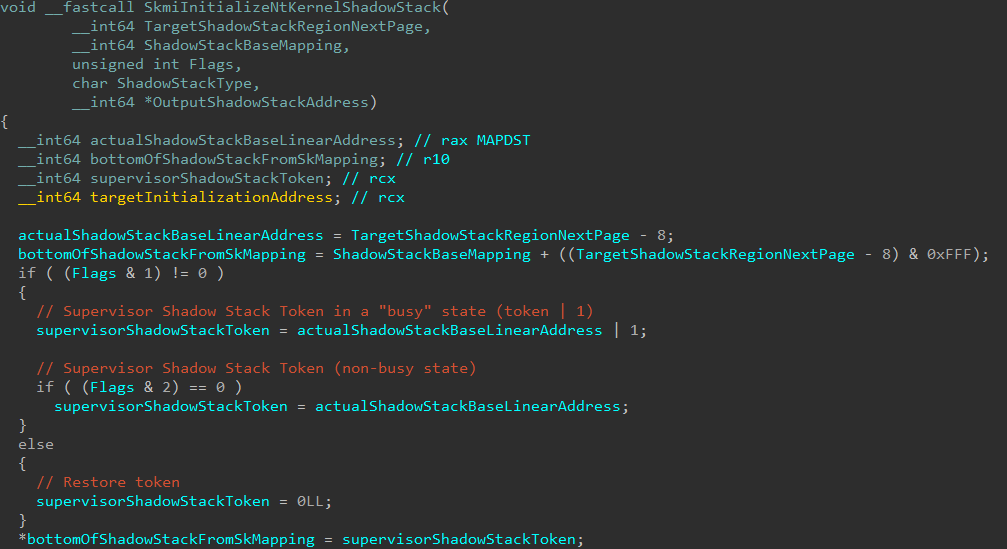
When a kernel-mode shadow stack creation operation is being processed by the Secure Kernel, it is the Secure Kernel’s job to configure the token. The token can be created with one of the following three states:
- A token is present, with the “busy” bit set, meaning this shadow stack is going to be active on a processor
- A token is present, with the “busy” bit cleared, meaning this shadow stack is not immediately going to be active on a processor
- A zero (NULL) value is provided for the token value
There are technically two types of tokens - the first is a “normal” token (with the busy or non-busy bit set), but then there is something known as a restore token. When the third scenario above occurs, this is the result of a restore token being created instead of an “actual” token (although it is possible to specify a configuration for both restore and “regular” tokens together).
A restore token is a “canary”, if you will, that the CPU can use to go and locate a previous shadow stack pointer (SSP) value. Quite literally, as the name infers, this is a restore point the OS (Secure Kernel in our case) can create during a shadow stack creation operation, to allow the current execution to “switch” over to this shadow stack at a later time.
A restore token is usually used in conjunction with a saveprevssp (save previous SSP) instruction in order to allow the CPU to switch to a new shadow stack value, while preserving the old one. When a restore operation (rstorssp) occurs, a restore token is processed. The result of the rstorssp is a returning of the shadow stack associated with restore token (after the token has been validated and verified). This allows the CPU to switch to a new/target shadow stack (there is a section in the Intel CET specification called “RSTORSSP to switch to new shadow stack” which outlines this pattern).
In our case (a user-mode thread’s kernel-mode stack) only the restore token path is taken. This actually occurs at the end of securekernel!SkmiInitializeNtKernelShadowStack.

Before I talk more on the restore token, I just mentioned the setting of the restore token occurs at the end of the initialization logic. Let us first see what other items are first configured in the initialization function before going into more detail on the restore token.
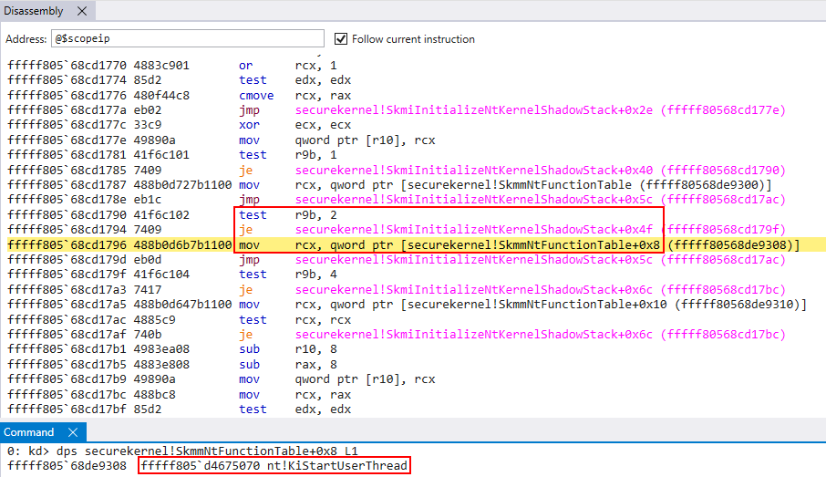
The other main item configured is the return address. This needs to be set where we would like execution to pick up back in VTL 0. We know a user-mode thread with a kernel-mode shadow stack is denoted as 2 in the Secure Kernel. The target return address is extracted from securekernel!SkmmNtFunctionTable, based on this flag value.
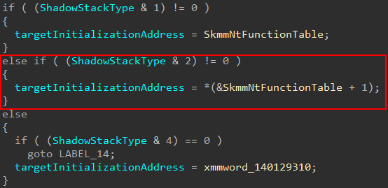
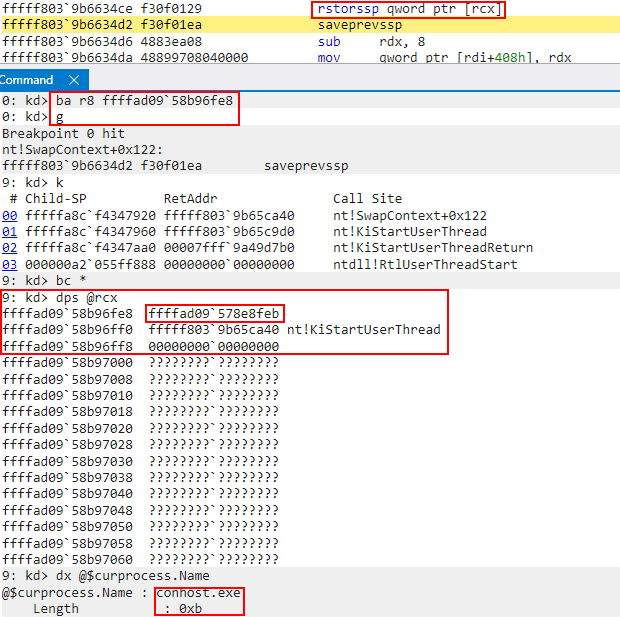
Using SourcePoint we can see this actually points to nt!KiStartUserThread in our case (Flags & 2 != 0). We can see this being stored on the target shadow stack (the SK’s current mapping of the target shadow stack is in R10 in the below image).
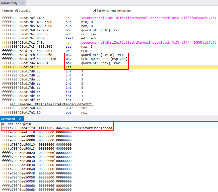
Right after the return address is copied to the shadow stack, this is also where also where OutputShadowStackAddress is populated, which is directly returned to VTL 0 as the target shadow stack in the VTL 0 virtual address space.
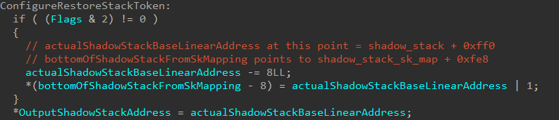
We can see that OutputShadowStackAddress will simply contain the address shadow_stack + 0xff0 (plus a mask of 1). This is, in our case, the restore token! The restore token is simply the address where the token is on the shadow stack (shadow_stack + 0xff0 on the shadow stack OR’d with 1 in our case).
In addition, according to the Intel CET specification, the lowest bit of the restore token is reserved to denote the “mode”. 1 indicates this token is compatible with the rstorssp instruction (which we will talk about shortly).
Going back to earlier, I mentioned this was a restore token but didn’t really indicate how I knew this. How did I go about validating this? I skipped ahead a bit and let the secure system call return (don’t worry, I am still going to show the full analysis of the shadow stack creation). When the call returned, I examined the contents of the returned shadow stack.
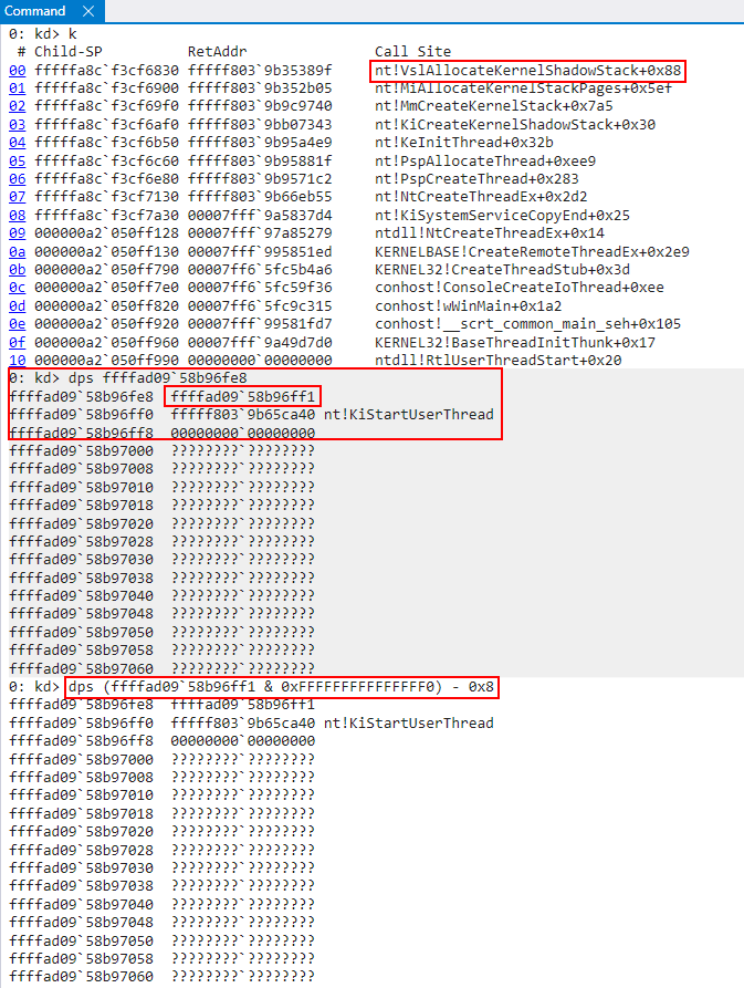
As we can see above, if we clear the lower bit of the restore token (which is reserved for the “mode”) and use this to dump the memory contents, this restore token does, in fact, refer to the shadow stack created from the secure system call! This means, at minimum, we know we are dealing with a supervisor shadow stack token (even if we don’t know what type yet). If this is a restore token, this token will refer to the “current” shadow stack (current in this case does not mean currently executing, but current in the context of the shadow stack that is returned from the target shadow stack creation operation).
To find out if this is a restore token we can set a break-on-access breakpoint on this token to see if it is ever accessed. Upon doing this, we can see it is accessed!. Recall break-on-access breakpoints break into the debugger after the offending instruction executed. If we look at the previous instruction, we can see that this was as a result of a rstorssp instruction! This is a “Restore Saved Shadow Stack Pointer” instruction, which consumes a restore token!
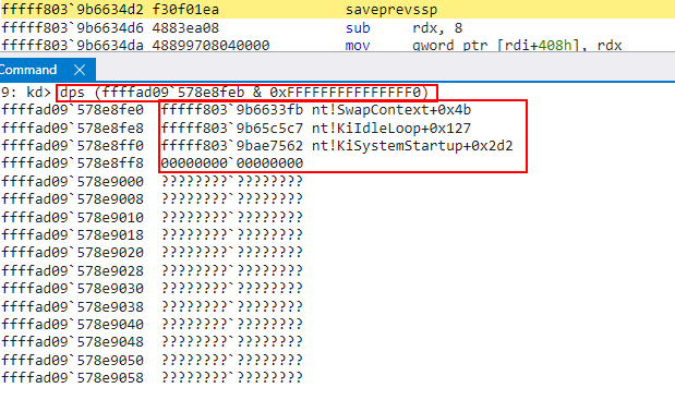
When a rstorssp instruction occurs, the restore token (which is now the SSP) is replaced (swapped) with a “previous SSP” token - which is the old SSP. We can see in the second-to-last screenshot that the restore token was swapped out with some other address, which was the old SSP. If we examine the old SSP, we can see the thread associated with this stack was doing work similar to our target shadow stack.
This outlines how the target shadow stack, as a result of the secure system call, is switched to! A restore token was created for the “in-scope” shadow stack and, when execution returned to VTL 0, the rstorssp instruction was used to switch to this shadow stack as part of execution! Thank you (as always) to my friend Alex Ionescu for pointing me in the right direction in regards to restore tokens.
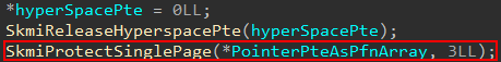
Moving on, after the initialization is achieved (the token and target return address are set), the Secure Kernel’s usage of the shadow stack is complete, meaning we no longer need the hyperspace mapping. Recall that this was just the Secure Kernel mapping of the target shadow stack. Although this page will be unmapped from the Secure Kernel’s virtual address space, these changes will still remain committed to physical memory. This can be seen below by inspecting the physical memory associated with the target shadow stack.
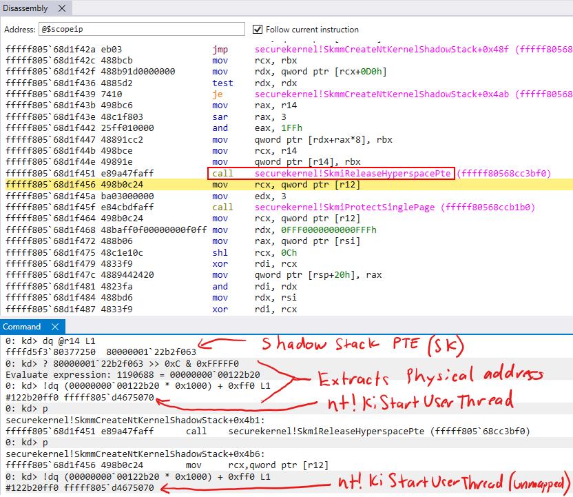
After the shadow stack is prepped, effectively the last thing that is done is for the Secure Kernel to provide the appropriate permissions to the associated physical page. This, again, is done through the HvCallModifyVtlProtectionMask hypercall by way of securekernel!SkmiProtectSinglePage.
All of the parameters are the same except for the flags/mask. HV_MAP_GPA_READABLE (0x1) is combined with what seems to be an undocumented value of 0x10 which I will simply call HV_MAP_GPA_KERNEL_SHADOW_STACK since it has no official name. The Intel SDM Docs shed a bit of light here. The (what I am calling) HV_MAP_GPA_KERNEL_SHADOW_STACK bit in the mask likely sets bit 60 (SUPERVISOR_SHADOW_STACK) in the EPTE. This is surely what 0x10 denotes in our 0x11 mask. This will mark the page to be treated as read-only (in context of VTL 0) and also treated like a kernel-mode shadow stack page by the hypervisor!
After the protection change occurs, this is the end of the interesting things which happen in the shadow stack creation process in the Secure Kernel! The shadow stack is then returned back to VTL 0 and the target thread can finish initializing. We will now shift our attention to some interesting edge cases where SK’s support is needed still!
Kernel Shadow Stack Assist Functionality
We have, up until this point, seen how a kernel-mode shadow stack is prepared by the Secure Kernel. Now that this has finished, it is worth investigating some of the integrity checks and extra verification the Secure Kernel is responsible for. There is a secure system call in ntoskrnl.exe named nt!VslKernelShadowStackAssist. This function, as we can see, is called from a few different scenarios of interest.
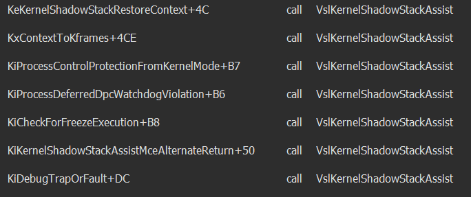
There are certain scenarios, which we can see above, where shadow stacks need legitimate modification. NT delegates these situations to the Secure Kernel since it is a higher security boundary and can protect against unauthorized “taking advantage” of these scenarios. Let’s examing one of these situations. Consider the following call stack, for example.
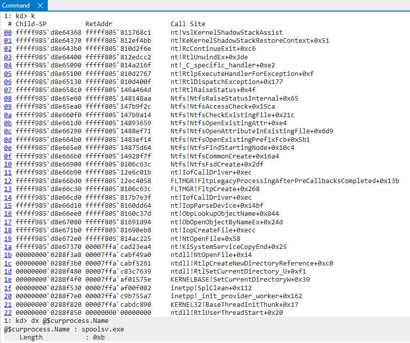
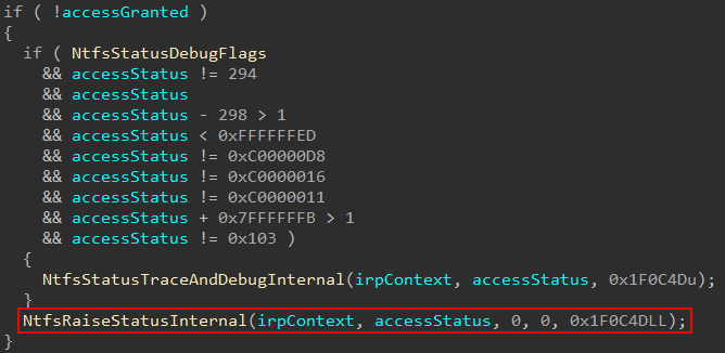
Here we can see, as part of a file open operation, the operation performs an access check. In the event the proper access is not granted, an exception is raised. This can be seen by examining the raising of the exception itself in NTFS, where the call stack above identifies this exception being raised from.
What happens in this scenario is eventually an exception is dispatched. When an exception is dispatched, this will obviously change the thread’s context. Why? Because the thread is no longer doing what is was previously doing (an access check). It is now dealing with an exception. The appropriate exception handlers are then called in order to potentially correct the issue at hand.
But after the exception handlers are called, there is another issue. How do we make the thread “go back” to what it was previously” doing if the exception can be satisfied? The way this is achieved is by explicitly building and configuring a CONTEXT structure which sets the appropriate instruction pointer (to the operation we were previously executing), stack, thread state, etc. One of the items in the list of things we need to restore is the stack. Consider now we have the implementation of CET! This also means we need to restore the appropriate shadow stack as well. Since the shadow stack is very important as an exploit mitigation, this is not work we would want delegated to NT, since we treat NT as “untrusted”. This is where the Secure Kernel comes in! The Secure Kernel is already aware of the shadow stacks, and so we can delegate the task of restoring the appropriate shadow stack to the Secure Kernel! Here is how this looks.
We can think of the steps leading up to the invocation of the secure system call as “preparing” the CONTEXT structure with all of the appropriate information needed to resume execution (which is gathered from the unwind information). Before actually letting execution resume, however, we ask the Secure Kernel to restore the appropriate shadow stack. This is done by nt!KeKernelShadowStackRestoreContext. We can first see that the CONTEXT record is already prepared to set the instruction pointer back to Ntfs!NtfsFsdCreate, which is the function we were executing in before the exception was thrown if we refer back to the exception callstack screenshot previously shown.

As part of the exception restoration process, the presence of kernel CET is again checked and an instruction called rdsspq is executed, storing the value in RDX (which is used as the second parameter to nt!KeKernelShadowStackRestoreContext) and then invoking the target function to restore the shadow stack pointer.
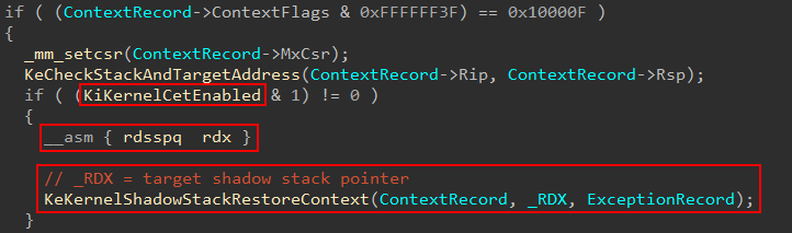
rdsspq is an instruction which will read the current shadow stack pointer. Remember, the shadow stacks are read-only in VTL 0 (where we are executing). We can read the shadow stack, but we cannot corrupt it. This value will be validated by the Secure Kernel.
nt!KeKernelShadowStackRestoreContext is then invoked. The presence of the mask 0x100080 in the CONTEXT.ContextFlags is checked.
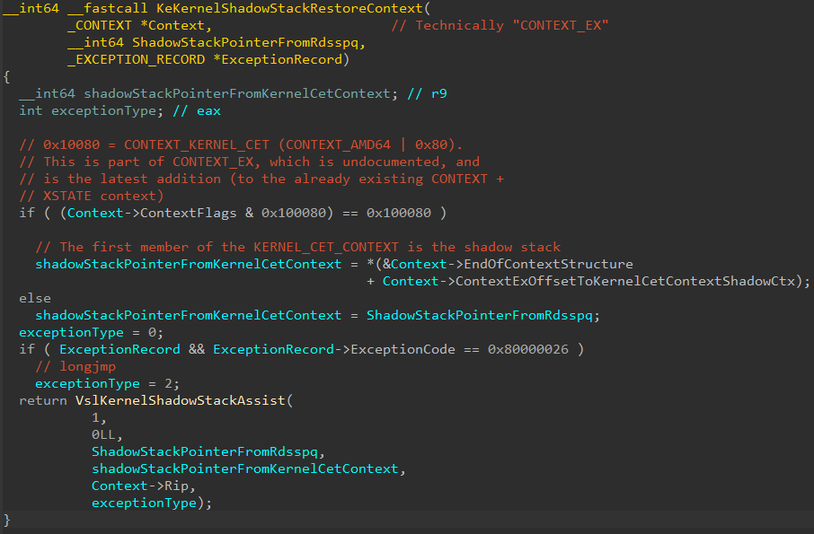
0x100080 actually corresponds to CONTEXT_KERNEL_CET, which is a value which was recently (relatively speaking) added to the Windows SDK. What does CONTEXT_KERNEL_CET indicate? CONTEXT_KERNEL_CET indicates that kernel shadow stack context information is present in the CONTEXT. The only problem is CONTEXT is a documented structure which does not contain any fields related to shadow stack information in kernel-mode. This is actually because we are technically dealing with an undocumented structure called the CONTEXT_EX structure, talked about by my friends Yarden and Alex in their blog on user-mode CET internals. This structure was extended to include a documented KERNEL_CET_CONTEXT structure. The KERNEL_CET_CONTEXT.Ssp is extracted from the structure and is also passed to the secure system call. This is to perform further validation of the shadow stack’s integrity by the Secure Kernel.
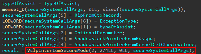
nt!VslKernelShadowStackAssist will then issue the secure system call with the appropriate information needed to validate everything and also actually set the restored shadow stack pointer (due to the exception). (Note that I call parameter 2 “optional parameter”. I am not actually sure if it is optional, because most of the time when this was a non-zero parameter it came from KTRAP_FRAME.Dr0, but I also saw other combinations. We are here to simply show functionality related to exceptions and we are not interested for this blog post in other scenarios).
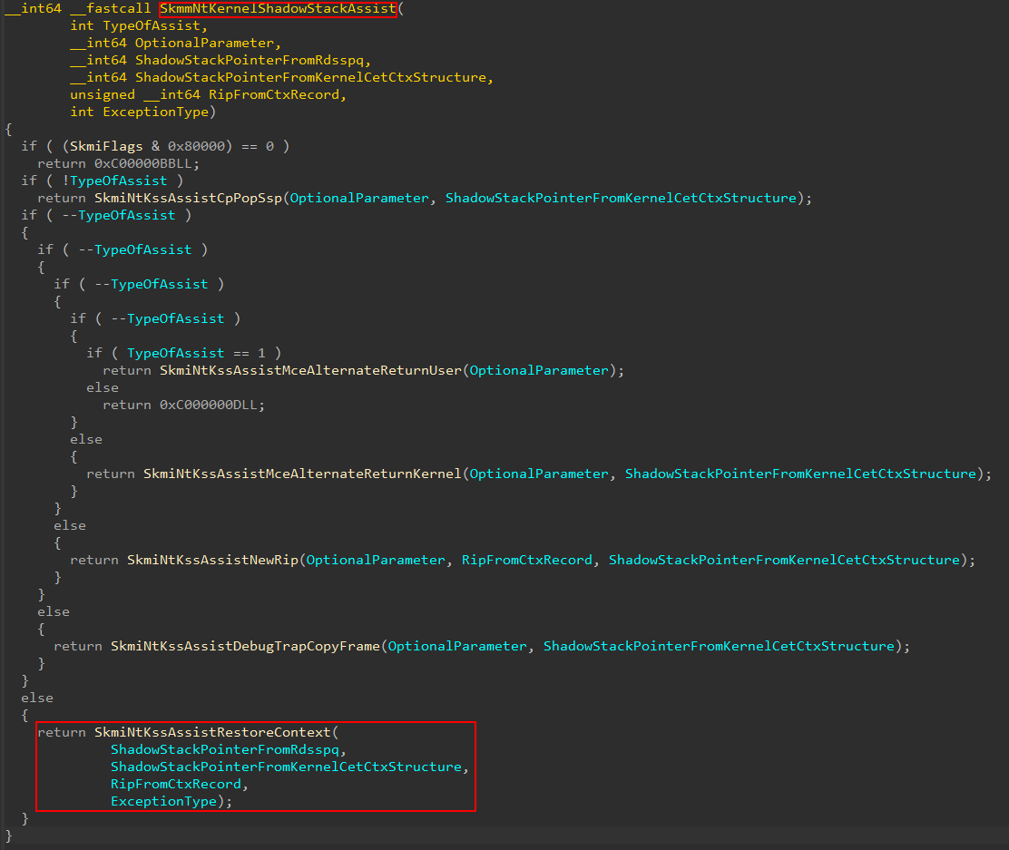
This will redirect execution in the Secure Kernel specifically at securekernel!SkmmNtKernelShadowStackAssist. In our case, execution will redirect into SkmiNtKssAssistRestoreContext.
securekernel!SkmiNtKssAssistRestore will perform the bulk of the work here. This function will call into securekernel!SkmiNtKssAssistDispatch, which is responsible for both validating the context record (and specifically the target instruction pointer) and then actually updates the shadow stack value. Anytime a shadow-stack related instruction is executed (e.g., rdsspq) the target shadow stack value is pulled from a supervisor shadow stack MSR register. For example, the ring 0 shadow stack can be found in the IA32_PL0_SSP MSR register.
However, we must remember, kernel CET requires HVCI to be enabled. This means that Hyper-V will be present! So, when the updating of the shadow stack value occurs via securekernel!SkmiNtKssAssistDispatch, we actually want to set the shadow stack pointer for VTL 0! Remember that VTL 0 is technically treated as a “VM”. The Intel CET specification defines the shadow stack pointer register for a guest as VMX_GUEST_SSP. This is part of the guest state of the VMCS for VTL 0! Thank you, once again, for Andrea for pointing this out to me!
How does the VMCS information get updated? When a given VM (VTL 0 in our case) needs to request the services of the hypervisor (like a hypercall), a vmexit instruction is executed to “exit out of the VM context” and into that of the hypervisor. When this occurs, various “guest state” information is stored in the per-VM structure known as the Virtual Machine Control Structure. The VMX_GUEST_SSP is now part of that preserved guest state, and ONLY the hypervisor is capable of manipulating the VMCS. This means the hypervisor is in control of the guest shadow stack pointer (the shadow stack pointer for VTL 0!). VMX_GUEST_SSP, and many of these other “registers” maintained by the VMCS, are referred to as a “virtual processor register” and can be updated by the hypervisor - typically through a vmwrite instruction.
As I just mentioned, we know we wouldn’t want anyone from VTL 0 to just be able to write to this register. To avoid this, just like updating the permissions of a VTL 0 page (technically GPA), the Secure Kernel asks the hypervisor to do it.
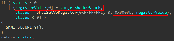
How does updating the guest shadow stack pointer occur? There is a generic function in the Secure Kernel named securekernel!ShvlSetVpRegister. This function is capable of updating the virtual processor registers for VTL 0 (which would include, as we just mentioned, VMX_GUEST_SSP). This function has been written up before by my friend Yarden in her blog post. This function has a target register, which is a value of type HV_REGISTER_NAME. Most of these register values are documented through the TLFS. The problem is the register type used in our case is 0x8008E, which is not documented.
However, as we mentioned before, we know that because of the operation occurring (restoring the shadow stack as a result of the context restore) that the VTL 0 shadow stack will, therefore, need to be updated. We know this won’t be IA32_PL0_SSP, because this is not the shadow stack for a hypervisor. VTL 0 is a “VM”, as we know, and we can therefore not only infer but confirm through SourcePoint that the target register is VMX_GUEST_SSP.
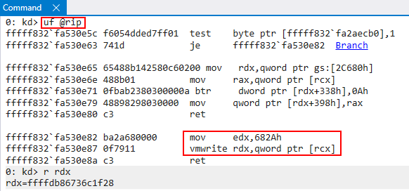
To examine the VMCS update the first thing we will need to do is locate where in hvix64.exe (or hvax64.exe for AMD systems) the operation occurs (which is the Hyper-V binary). A CPU operating in VMX root mode (the CPU is not executing in context of a VM) can execute the vmwrite instruction, specifying a target virtual processor register value, with an argument, and update the appropriate guest state. Since hvix64.exe does not contain any symbols, it was fairly difficult for me to find the location. Starting with the Intel documentation for CET, the target value for VMX_GUEST_SSP is 0x682A. This means we need to locate anytime vmwrite occurs to this value. When I found the target address in hvix64.exe, I set a breakpoint on the target function. We can also see in RDX the target guest shadow stack pointer the Secure Kernel would like to set.
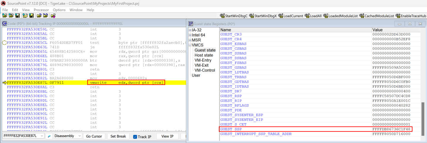
We then can use the actual SourcePoint debugger’s VMCS-viewing capabilities to see the VMX_GUEST_SSP updated in real time.
Before:
After:
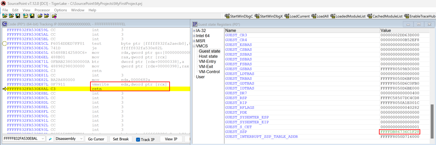
This is how the Secure Kernel emits the hypercall to update the VMX_GUEST_SSP in VTL 0’s VMCS guest state in situations where something like a context restore operation takes place!
Thank you to my friends Alex Ionescu, Andrea, and Yarden for helping me with some questions I had about various behavior I was encountering. This is the end of the restore operation, and securekernel!SkmmNtKernelShadowStackAssist will eventually return to VTL 0!
Conclusion
I hope you found this blog post informative! I learned a lot writing it. I hope you can see why, now, the Secure Kernel is required for kernel-mode shadow stacks on Windows. Thank you to Alan Sguigna for sending me the powerful SourcePoint debugger and my friends Andrea, Yarden, and Alex for helping me understand certain behavior I was seeing and answering questions! Here are some resources I used:
- Intel CET Specification Documentation
- https://cseweb.ucsd.edu/~dstefan/cse227-spring20/papers/shanbhogue:cet.pdf
- Intel SDM
- https://xenbits.xen.org/people/andrewcoop/Xen-CET-SS.pdf