Windows ARM64 Internals: Exception & Privilege Model, Virtual Memory Management, and Windows under Virtualization Host Extensions (VHE)
Introduction
About 5 years ago I put out a blog post about 64-bit “memory paging” on a standard Intel x64-based Windows machine when I was first starting to learn about Windows internals. Looking back at this post, as I was getting started learning Windows internals, I felt I left a lot to be desired - and I wanted to do something about it without re-inventing the wheel.
It is really “unsaid” these days that any sort of Windows analysis, de-facto, infers you are operating on an x64 machine - usually an Intel-based one. There is very little “out there” about Windows internals on ARM64. Given this fact, I thought it would be interesting to do a similar post with all of the “Windows-isms” that come along with the ARM64 architecture - specifically on the new Surface Pro with the Qualcomm Snapdragon X Elite processor. This would allow me to talk about things I did not get to at the time of my Intel-based blog, without regurgitating already existing information. Specifically this blog post will go over:
- Exception and privilege levels (ARM64 “version” of “rings” on x86 processors)
- Windows hypervisor behavior (and, therefore, also OS behavior due to VBS) under ARM’s Virtualization Host Extensions (VHE)
- Using WinDbg to access ARM system registers using the
rdmsrcommand (yes, you read that right! Using the “read MSR” command!) - TrustedZone and Windows VTL co-habitation
- Windows-specific implementation of virtual memory: paging hierarchy, address translation, etc.
- ARM-specific PTE configuration on Windows (e.g.,
nt!MMPTE_HARDWAREdifferences between x64 and ARM64) - Self-referential paging entries (like self-reference PML4, but for ARM’s “level 0” page table) and management of PTEs in virtual memory
- Translation Lookaside Buffer (TLB) and context switching
- Other “Windows-isms” such as Windows configuration of certain features, like hypervisor behavior, virtual memory behavior, etc.
This blog post was conducted on a processor which “runs” the ARM v9 “A-profile” architecture, along with an installation of Windows 11 24H2. This blog post assumes readers are already familiar with concepts such as “virtual” and “physical” memory. Additionally, this will not be an “ARM history” blog post, we will be picking right up with the ARM v9 (specifically ARM v9-A) architecture.
Lastly, this post will not include things like interrupt handling, exception dispatching, or system call handling mechanics. I hope to do a post specific to these soon.
Exception/Privilege Model
ARM, unlike Intel, does not leverage what is know as the traditional “privilege” levels (e.g., PL 3, for user-mode, and PL 0, for kernel-mode). These are often referred to as “rings”. ARM instead refers to a processor that is “running” at a particular exception level (which is also responsible for enforcing privileges similar to “ring levels”). This is because ARM64 uses an exception-based architecture. What I mean by this is effectively “everything” is an exception; from special instructions like svc (which is referred to as a “supervisor call” and is the ARM64 version of a system call) which simply induces a particular type of exception; all the way to an interrupt (yes an interrupt is considered an exception on ARM!). This is because ARM refers to an exception as “any condition that requires the core to halt normal execution and execute a dedicated software routine”.
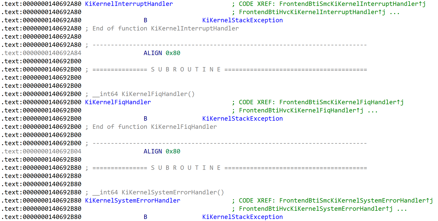
The ARM architecture sees that software stores a vector of exception handlers in the VBAR_ELX system register (similar to a control register or also an MSR on x86), with X denoting the exception level. For example, all of the exception handlers for the processor running at exception level 1 (effectively “kernel mode”) are stored in the VBAR_EL1 system register. On Windows, the vector for the exception handlers - tracked through the symbol nt!KiArm64ExceptionVectors - is stored in this system register. A few of them can be seen below, such as the user exception handler, the interrupt handler, and fast interrupt request handler (FIQ).
ARM currently defines 4 main exception levels - exception level (EL)3 - EL0. For ARM the terminology is inverse to that of Intel. The lower the number, the less privileges. For example, EL0 refers to “user-mode”. What is particularly interesting about ARM is that, unlike Intel - which really only uses privilege level 0 for kernel-mode and privilege level 3 for user-mode - all of the exception levels have a documented purpose (although they do not have to be used for their documented purpose). This even includes the hypervisor! The hypervisor, on Intel-based systems, is often (mistakenly) referred to as “ring minus 1”, or “ring -1”. There is no architectural support for a “ring -1” on Intel systems - the hypervisor simply runs at ring 0, but in a different mode (VMX root). However, on ARM-based systems “exception level” 2 is documented as reserved for the hypervisor.
The exception level, just like “ring levels”, gives credence to what types of privileged actions are allowed. Just as in the case of Model-Specific Registers (MSRs) on x86-based processors, many system registers are only accessible at certain exception levels (although, not all of them are only accessible at a “higher-privileged” EL. For example, some EL1 system registers can still be “accessed” by EL0. Additionally, some EL2 registers can be accessed from EL1, although the operations may be trapped to the hypervisor in EL2). In addition, certain memory regions are only accessible at certain exception levels.
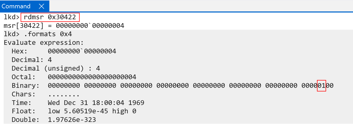
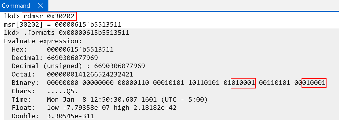
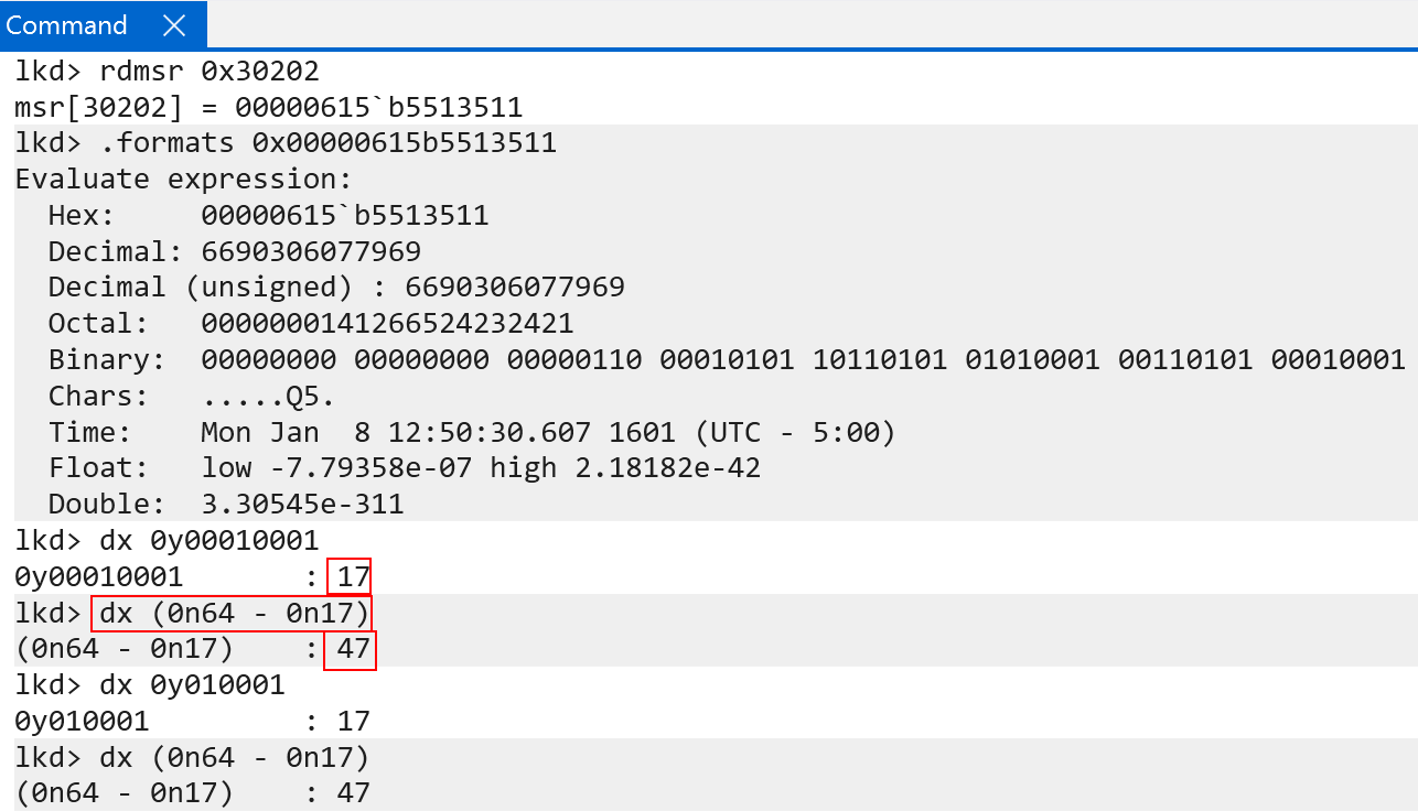
The “current exception level” is stored in the CurrentEL system register. This can be examined with WinDbg, although WinDbg has an odd way of fetching the value of the system register. Through trial-and-error it was discovered it is possible to read ARM system registers using the rdmsr command in WinDbg and passing in the documented encoding values found in the ARM documentation - encodings are similar to an “MSR address/identifier”. In this case, the encoding for the CurrentEL register is:
0b11(3)0b000(0)0b0100(4)0b0010(2)0b010(2)
This gives us a total value of total value of 30422. Passing this as a constant hex value (0x30422) to the rdmsr command allows reading the target system register.
The CurrentEL registers documents that bits 0 and 1 are “reserved” bits (so the “current EL” starts, technically, at bit 2 and goes through bit 3). In our example, the current EL is 0b01 (disregarding bits 0 and 1) for both a local kernel debugger (execution in kernel-mode) and while in user-mode (more on this in a few paragraphs).
The exception level, when execution is in kernel-mode, is that of 0b01 - or EL1. This makes sense as ARM documents that the privileged part of the operating system (e.g., the kernel) runs in EL1. We should, however, bear in mind that modern Windows installations (even on ARM64) are virtualized - and there is “more than what meets the eye” because of this. This means it is worth briefly talking about the hypervisor/OS design on ARM64 Windows systems.
Windows and Virtualization Host Extensions (VHE)
Newer ARM processors (starting with ARMv8.1-A and higher) have support for VHE, or “Virtualization Host Extensions” - which is a feature that extends what capabilities are afforded to exception level 2 (EL2) - which is where the hypervisor runs.
VHE, which seems to have been developed with Linux and type-2 hypervisors in mind, specifically allows one to optionally run an entire host operating system in EL2. This means both the hypervisor and guest OS are in the same exception level. The reason why one would want to do this makes a lot of sense. A type-2 hypervisor, without VHE, typically would run in EL1 as a kernel software package. Since EL2 is “for the hypervisor” this means that there is a constant switching between EL1 and EL2 in order to preserve system register state across VMs entering/exiting, caches constantly being flushed - and other items not mentioned here - resulting in more performance degredation. Placing the host OS and the hypervisor in the same exception level results in far fewer guest <-> hypervisor context switches. In addition, there are other gains to be had.
“Pre-VHE” EL2 only had 1 page table base register, limiting the amount of address space EL2 can use and making it almost impossible to put a host OS, which is what VHE does, in EL2 since a host OS needs to also typically run user-mode applications in addition to a kernel. We will talk more about this later, but the page tables are “split” between kernel/user page table roots - meaning “pre-VHE” EL2 can only address half of what EL1 is capable of doing (and meaning that there is not enough “room” to host all of the user-mode things an OS needs to support). VHE, on the other hand, extends the number of page table root registers to 2 for EL2 - effectively giving EL2 and almost identical paging nomenclature to EL1 - and allowing both user-mode and kernel-mode to both be addressable “in the same way”. Lastly, a nice feature called “system register redirection” is present via VHE, which does the following:
- The “real” contents of the EL1 registers (e.g., the EL1 registers used by anything actually running in EL1) can be found via a new set of “aliasesed” registers appended with
EL12andEL02from EL2 itself. This allows EL2 direct access to EL1 system register contents without needing to preserve them/re-populate them across context switches. - Most accesses to
EL1registers (meaning not using theEL12registers, but the “literal architectural” EL1 registers) transparently redirect to their EL2 variants. This is a product of VHE being designed in a way that does not require many changes to an operating system that previously ran in EL1 (accessing EL1 registers) which will now run in EL2 via VHE. Remember - if you are a host OS kernel you are usually in EL1 (without VHE). If you put that kernel in EL2, you would need to re-write all of your system register access code to update EL1 accesses to EL2. System register redirection avoids this, allowing software to still access EL1, in EL2, and “magically” have the hardware access what you intend to access - which is EL2 (since the software is now running in EL2). This also means, for example, that if you parse Hyper-V for accesses to the EL2 page table root system registers - you will never find such an operation. Instead you will only see accesses toTTBRX_EL1which is then redirected to the “EL2 equivalent” in hardware (e.g.,TTBRX_EL2). WithHCR_EL2.E2H(VHE) set, EL1 accesses (actual EL1 registers, not the EL12 and EL02 registers) are redirected to EL2 equivalents.
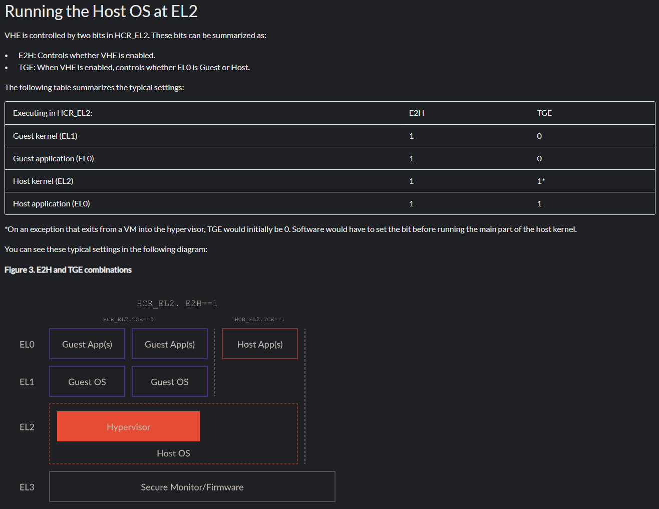
As mentioned, VHE really has type-2 hypervisors in mind - meaning that, on purpose, EL1 is left void of all software except the kernel of a guest, which runs in EL1. Below is a helpful chart produced by ARM to outline this setup. E2H and TGE (traps all exceptions from EL0 to EL2 since the host would now be running in EL2 instead of EL1 and, as a result, things like system calls need to go from EL0 to EL2 now instead of EL1) define the behavior here. The “gist” is that EL1 is for the guest kernel to run, not the “host kernel”.
Windows, however, breaks this mold. Although VHE is configured in Hyper-V, Windows still uses EL1 for the actual operating system/NT kernel by design. This means that both guest kernels (VMs) and the NT kernel run in EL1. This is because, again, we are running under VBS. With the hypervisor enabled NT lives in the root partition (with actual VMs being in child partitions). In this case both root partition and guest partition are treated as “guests” in the sense that both have memory access gated via SLAT (“stage 2 tables” on ARM) - although pages in the root partition are simply identity-mapped. I have talked about the configuration of the root partition and identity-mapped pages in a previous blog on HVCI. EL1 is for both the root partition (NT kernel) and child partitions(s) (VMs), with the hypervisor not making a “distinction” between them when allowing a “guest” to run in EL1.
This, however, is still not the main/actual reason why VHE is configured on Windows systems. Although Windows/Hyper-V configures VHE - it is obviously not to gain the “benefit” of having the host OS also run at EL2 (because, as we have seen, it doesn’t). The main reason VHE is configured for Windows is to instead to allow software running in EL2 to gain the benefit of the software “behaving” as if it were running in EL1. EL2, as an example, has a different “page table schema” than EL1 without VHE enabled (and, therefore, can only address half the memory as EL1 can). With VHE, however, two roots are in place (TTBR0_EL2 and TTBR1_EL2). Other benefits include system register redirection and maintaining a firm boundary between the kernel (EL1) and hypervisor (EL2). Effectively, EL2 makes software in EL2 “behave” more like software that runs in EL1 - by affording it all of the benefits (and more) that I just mentioned. To examine this further, we can look at Hyper-V in more detail.
Hyper-V is responsible for configuring the hypervisor settings for the ARM machine (although winload.efi performs some configuration as well). Taking a look at the ARM64-based Hyper-V binary (hvaa64.exe) we can see that the hypervisor configuration register, HCR_EL2, has a hardcoded configuration mask of 0x400000018 when Hyper-V begins (although the configuration can be updated). The upper nibble (4) in this case corresponds to bit 34. In the HCR_EL2 hypervisor configuration system register documentation this corresponds to E2H feature. E2H stands for “exception level 2 host”. This means that if the bit is set (HCR_EL2.E2H) there is support for VHE. Notice, additionally, HCR_EL2.TGE is not set. This would be necessary if, for instance, the host OS ran in EL2 - as exceptions would then need to be trapped into EL2. They do not, under Windows, because EL0 (user-mode) <-> EL1 (kernel-mode) is still valid. Almost all exceptions (svc instruction, etc.) are trapped into EL1 from EL0. We don’t want to trap EL0 into EL2, as for one the NT kernel runs in EL1, but we dont want to enter the hypervisor so often.

To reiterate: with VBS and Hyper-V enabled and HCR_EL2.E2H (VHE) enabled the host OS and NT kernel still run in EL1.
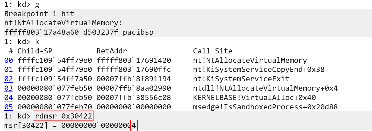
We have taken a bit of a detour, so let’s get back to where we were - exception levels. Traversing backwards for a second we can recall earlier that the exception level, when execution was in user-mode, was EL1 and not EL0 via WinDbg. Let’s now talk about why this is. The answer is very simple actually, and it has to do with the way we are querying it (hint, the current EL really is EL0!). The reason why we see EL1 has to do with how the rdmsr command in WinDbg works. When rdmsr is executed, this will actually invoke a kernel function (specifically nt!KdpSysReadMsr). It is therefore the kernel which executes the register read. Since the read will always happen in kernel-mode, the current exception level will always be 1 in the eyes of the rdmsr command. To get the “real” value in user-mode we can instead write a basic application to read the current exception level register in user-mode (which, again, goes back to what I mentioned earlier - some system registers can be read from EL0/user-mode).
//
// ARM64_SYSREG is defined in winnt.h.
// _ReadStatusReg is defined as an intrinsic function in intrin.h.
//
const int currentElReg = ARM64_SYSREG(3, 0, 4, 2, 2);
wprintf(L"[+] CurrentEL: %llx\n", _ReadStatusReg(currentElReg));
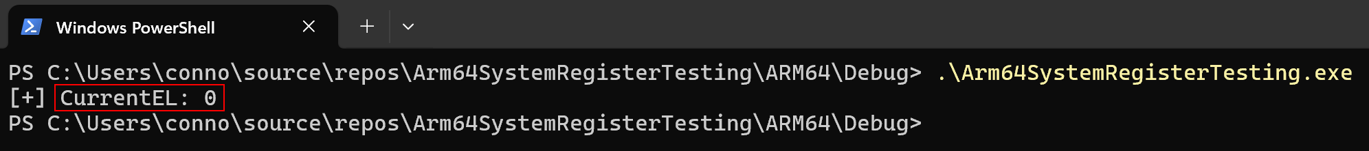
In addition to exception levels, ARM has another item of interest in the execution model which helps define privileges - the “security state”. We will briefly talk about it, as it is not used on Windows.
Security States: Secure Vs. Non-Secure
I would like to preface this section to say that is is, effectively, not applicable for Windows - but it is worth a small blurb.
A feature called TrustZone, on ARM, is present in order to to split out the computer into two “states”: secure and non-secure state. These are self-explanatory terms - some parts of the computer we want to “hide away” from non-secure portions of the computer. For example, “secure state” has access to both secure and non-secure state memory, system registers, etc. However, non-secure state only has access to non-secure state memory, system registers, etc.
Secure and non-secure states are similar in concept to that of VTL 0 and VTL 1, where certain regions of memory (secure state memory) are isolated from less-trusted entities (like non-secure state memory). There is a special exception level, exception level 3 - the secure monitor - which is responsible for facilitating transitions between secure/non-secure state and also handles requests for Secure Monitor Calls (SMC) - which effectively is a special instruction that causes an exception into EL3. This allows, for instance, non-secure world to communicate with secure world.
Since Windows has its own concept of secure/non-secure (VTLs), “secure state” is not used on Windows (Windows never really touches EL3). This is corroborated by the following statement from Windows Internals, 7th Edition, Part 2:
Although in Windows the Secure World [Secure state] is generally not used (a distinction between Secure/Non-secure world is already provided by the hypervisor through VTL levels), …
More information about security states can be found here.
Current Execution State
Before ending this portion of the blog, related to system architecture, there are two other points of contention to bring up. On an x86 system, the current “processor block” is always accessible through the gs segment register. However, ARM does not have the concept of segmentation in the same way that x86 does. Because of this, we need a new way to store “the current” processor block, thread, etc.
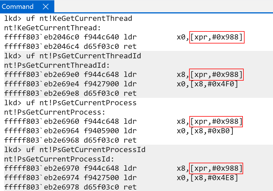
On Windows ARM systems, Windows treats the X18 (called XPR as well, or “platform register”) register as a reserved register. This always points to the current KPCR structure in kernel-mode and, in user-mode, always points to the current TEB structure.
There are, however, some “other” registers which are used to store OS/thread-specific information. ARM documentation defines this as “OS-use” and, therefore, “not used by the processor”. They are up to the discresion of the OS:
TPIDRRO_EL0(current CPU -> accessible in EL0)TPIDR_EL1(currentKPCR)TPIDR_EL0(reserved)
Windows still uses X18/XPR when calling macros, for instance, that “get” the current KPCR instead of using the system register.
Windows Virtual Memory Internals - ARM64 Edition
Let’s now start talking about virtual memory internals and paging on ARM!
Before going further, however, it is probably prudent to mention the ARM version of “Second-Level Address Translation” since it is an important topic (as VBS always results in SLAT being used) and since it is not the primary topic of this blog post. ARM refers to SLAT as “stage 2” translations. With virtualization enabled the concept of “extended” page tables still applies to ARM, although the terminology differs. As you may know, Intel leverages extended page tables (EPTs) to facilitate isolation and translation of memory “in a guest” to actual system physical memory. ARM has a similar concept, with “stage 1” translation referring to “intermediary” translations - being that of a virtual address to that of an “intermediary” physical address (similar to guest physical address on Intel). However, if a hypervisor is not present, stage 1 instead converts virtual addresses into actual physical addresses (since no hypervisor is present) and no further translation is needed. If a hypervisor is present, typically then what is known as “stage 2” translations will occur - where the previously-genereated intermediary physical address (IPA) is converted into actual physical memory (similar to GPA -> SPA on Intel). So although in our example we will show the NT kernel facilitating the translation, technically these are all “IPA”, or intermediate physical addresses. However, memory in NT is identity-mapped - meaning that the root partition can still access “real” physical pages since all of the “guest” physical memory corresponds directly to system physical memory - although memory access is technically gated by stage 2 table translation.
Let’s now explore the virtual memory implementation on an ARM-based version of Windows!
Paging Hierarchy
ARM-based processors also have a paging hierarchy similar to that of Intel. Standard 64-bit Intel machines today have 4 levels of paging, with LA-57 processors capable of implementing 5 levels (although this is beyond the scope of this blog post, as well as ARM’s own 52-bit and 56-bit implementation). This means that there are four page tables used in the virtual-to-physical address translation process on ARM64 when 4 levels of paging are involved.
Unlike Intel, ARM lets the operating system have more “of a say” in the configuration of what kind of translation schema will be in-use (of course, only if the architecture supports it, which can be determined via the ID_AA64MMFR0_EL1 system register). What I mean by this is a specific translation granule is defined in a system register - which effectively defines the level of granularity that the final page in the memory translation process has, otherwise referred to as “the smallest block of memory that can be described”. This effectively means the size of a page is the granule. Just like Intel, each paging structure “addresses” a certain range of memory (e.g., table X describes 1 GB of memory, for example). The “last” or “final” paging structure typically describes the smallest unit of memory/final page - which is usually 4KB on 64-bit systems.
The most common example of this, on a 64-bit operating system, is 4KB - meaning translations, when the granule is 4KB, result in mapping a final, 4KB-sized physical page. Granules have a more specific meaning, however, and that is the granule helps to define which bit in a virtual address corresponds to the first index into the first page table.
There are typically 4 tables used for translation on most modern ARM64 machines. This can be seen below, and is taken from the ARM documentation found here.
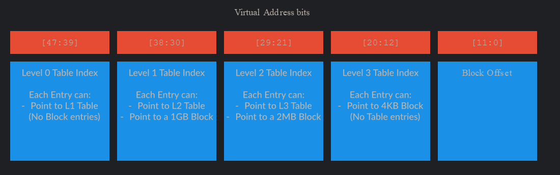
Instead of “PML4, etc.” the tables are named Level 0/1/2/3 - with the final step being a computation of an offset from the “last” table index (which is the index into the level 3 table). Each table is responsible for mapping portions of the entire VA space - just like Intel-based systems. As an example, just like Intel systems, the root page table (under the Windows 4KB granule schema) addresses 512 GB. This is because each page table still has, like Intel-based systems, 512 page tables (again, when 4KB pages are used. This changes when the granule does). Since Level 1 contains “1 GB mappings”, this means level 0 can contain 512 “level 1 entries” or “1 GB mappings” - meaning level 0 can address 512 GB of virtual memory.
Using the debugger, we can validate investigate where in the virtual address we must begin for the translation process. This location is defined by the architectural limit (64-bits in this case) and the granule. The granule on my machine is set to 4KB, and is denoted by the system register value TCR_EL1.TG0 and TCR_EL1.TG1 (we will see why there are effectively “two” versions of everything, including page table root system registers shortly).
With the architectural limit and granules known, we then can turn our attention to, again, the TCR_EL1 system register, specifically the TCR_EL1.T0SZ (bits 0 - 5) and TCR_EL1.T1SZ (bits 16 - 21) values define which bit in the virtual address that represents the “true” size of the virtual address. TCR_EL1.TXSZ determines the most significant bit used in the VA translation process (e.g., the first bit used in the calculation for the first table index). On Windows for ARM, the values of TCR_EL1.TXSZ are both 0x11, or 17 decimal. Taking the full size of a VA (64) and subtracting from it 17 yields a value of 47. This means the 47th bit (technically position 46, since we index from 0 - e.g., 46:0) is the first bit we need to locate for the translation process. What this means is that Windows technically employs 47-bits for tranlsation on ARM - unlike x64 systems that typically employ 48-bits for translation (notice I am referring to “bits used for translation” not the actual size of the address). Although on 47-bits are used for translation on Windows systems, Windows on ARM64 is still considered as using 128 TB of memory for user-mode and 128 TB of memory for kernel-mode - effectively meaning that although 47-bits are used for translation the addresses themselves are treated as “48-bit”. This is because although only 47-bits are used for translation, the 48th bit (meaning bit 47 from position 0) and onward are still actually used still to denote user/kernel (technically bits 63:47, which is “bit 64 to bit 48” since we index from 0 denote user/kernel). Because of this, bit “48” is still relevant, but not used for translation purposes. On Intel, the 48th-bit not only denotes user/kernel but is still used in the translation process. This means that also ARM addresses are “relevant” through bits 47:0 - the same as Intel - and therefore we can say the address space is still the same (128 TB for user-mode and 128 TB for kernel-mode) even though only 46 of the bits are used for translation on ARM, as there is a dedicated bit (series of bits technically) for selecting either the kernel or user page tables (there are two page table roots on ARM in EL1), whereas Intel uses bit 47 to denote both user-mode and kernel-mode and also the first significant bit in the translation process.
As an aside, we will talk more in a second why there are two “page table roots”. Conceptually, we can say that the page table root is similar to the CR3 register on x86-based systems, and the TXSZ bit defines where in the virtual address we start for the first page table lookup.
Page Table Roots And Memory Configuration
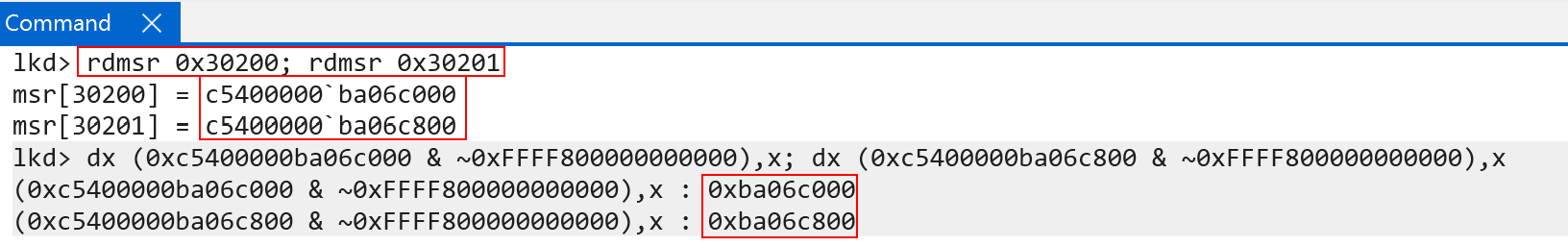
One of the distinct differences on ARM systems is the boundary between user-mode and kernel-mode memory. Instead of “just” using a certain bit to denote the “lower” and “higher” address ranges ARM actually breaks out the page table roots for “lower” (user-mode) virtual addreses and “higher” (kernel-mode) addresses (although, technically, the “48th bit” is partly still responsible for determining which page table root is used in the table walk - and thus it can still be said that this bit also denotes user/kernel). TTBR0_EL1 is the user-mode root and TTBR1_EL1 is the kernel-mode root. For the user-mode root, bits 1 - 47 are the physical address of the page table root. Bit 0 refers to the Common not Private bit. On Windows, this is always set to 0. Common not private refers to the fact that address and VM identifiers (which we will talk about shortly) can be shared across different processors. In fact, the Microsoft Surface Pro machine on which this blog was done does not even support CnP (via ID_MMFR4_EL1). This means that we can effectively treat bits 47-0 as the base root table physical address (similar to CR3 on x86) for TTBR0_EL1.
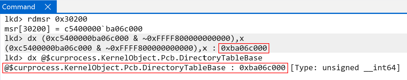
Every user-mode process on Windows on ARM still carries “their” per-process page table root in KPROCESS.DirectoryTableBase. This value, on context switch, is then loaded in to the TTBR0_EL1 system register - which maintains the “current” lower (user-mode) address space. This is how Windows on ARM, identically to x86, maintains a private process address space when a particular process is executing.
Two questions likely stand out:
- Why is the “higher” (kernel) portion being computed from an offset of the user-mode page table root? Why would the user-mode root have any bearing on the kernel-mode root?
- Additionally, what is ASID, and why is it used in storing the both page table roots?
The latter question is probably best-suited to be answered first. ASID, or Address Space Identifier is a very neat ARM concept. This allows effectively allows the system to “tag” translations (e.g., a translated virtual address) with an ASID. This associates a translation with a process. We will talk more about the Translation Lookaside Buffer (TLB) later, but the ASID is important to the TLB on ARM!
Coming back to the first question - why is the kernel page table root being configured in such a way? This comes as a result of TTBR1_EL1 having a slightly different implementation on Windows and also the way Windows works in general - as well as some differences between ARM and Intel architectures.
Let’s talk first on how the address translation works. Earlier I mentioned that on ARM64, for Windows, translation starts at bit 47. The first table lookup (level 0) would theoretically be bits 47-39. However, this is one of the nuanced differences between x86 and ARM. Bit 47 helps to denote which page table root to use. So technically it is used in the translation process, but it is not used as an index into the first table. This means that bit 47 is “ignored” in the sense of being used to compute the index into the level 0 table. Why does this matter?
The addition of the value 0x800 to kernel page table root (TTBR1_EL1) from the user-mode root (TTBR0_EL0) is really the addition of “half” a page, which is 2048 decimal bytes. This means the addition of 0x800 bytes to TTBR1_EL1 is a compensation for the fact that bit 47 is not used in the translation process. Recall that each page level has 512 entries. This is capable of addressing both the entire user-mode and kernel-mode virtual address space. So, the 512 entries are now split between both page table roots. The user-mode portion is in TTBR0_EL1 (first 256) and the kernel-mode portion is in TTBR1_EL1 (second 256) - for a total of 512 entries between them, split across 1 page of memory (e.g., 1 page of memory contains the 512 entries, 256 in each “half”, or 0x800).
On ARM, just like x86, a page table entry is sizeof(ULONG_PTR) - which is 8 bytes. So, 256 * sizeof(PTE) (which is 8 bytes) gives a value of 2048 in decimal, or 0x800 in hex! This means the “second half” of the level 0 table/page table root - which is the kernel-mode portion - would come after the first 256 entries. Since 256 entries take up 0x800 bytes - this is exactly why the kernel-mode portion starts at TTBR0_EL1 at offset 0x800! Additionally, this means the “kernel-mode” portion of the page table root is also always swapped out on context switch - and does not just remain as a “flat” table for all kernel-mode memory. This is because a process on Windows may be executing in context of a particular process, but doing so in kernel-mode. An example of this is a system call transitioning into kernel-mode, but executing on the same thread which issued the system call. Because of this, even though kernel-mode memory has access to user-mode memory, it continues to do so in context of a particular private process address space. Since the page tables are per-process, Windows simply does the following (taken from Windows Internals, 7th Edition, Part 1):
To avoid having multiple page tables describing the same virtual memory [the shared kernel memory], the page directory entries that describe system space are initialized to point to the existing system page tables when a process is created.
So although there is a “per-process” kernel page-table root (TTBR1_EL1), which is updated every context switch, the entries all mostly point to the same physical memory (meaning the kernel mappings are mostly “shared” across processes). This can be seen below. Using !vtop (though we will still show manually translating an address later) with two separate page table roots all of the paging structures used for translations are the exact same for a kernel-mode address - minus the first index (indexing level 0, which is the root. This is expected, because each process has a different base root address - but the rest of the physical addressing structures are the same, because they are simply copies):
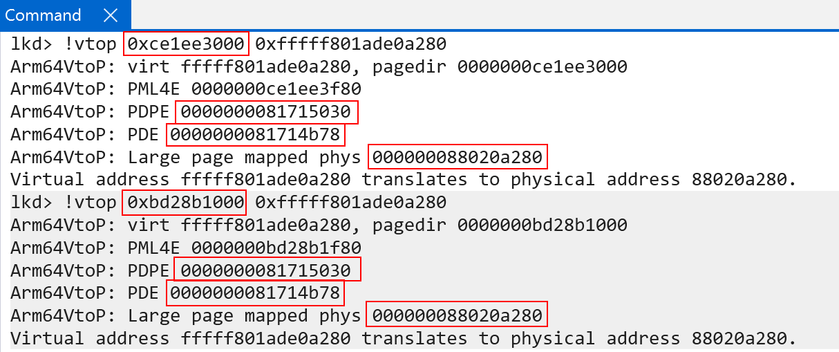
We will see later on additional reasons why it is best to keep the system mappings as “per-process” when we talk about Address Space Identifiers (ASIDs).
Translation Process
Let’s now, as an example, translate a kernel-mode virtual address with the knowledge we now have! Let’s attempt to translate the address of the kernel-mode function CI!CiInitialize using the page table root of our current process. Here I am using a local kernel debugger, so the debugger is always “in context” of the “current process” - which is EngHost.exe. This means the ARM system registers holding the page table roots, in my debugger, will always be “my own”.
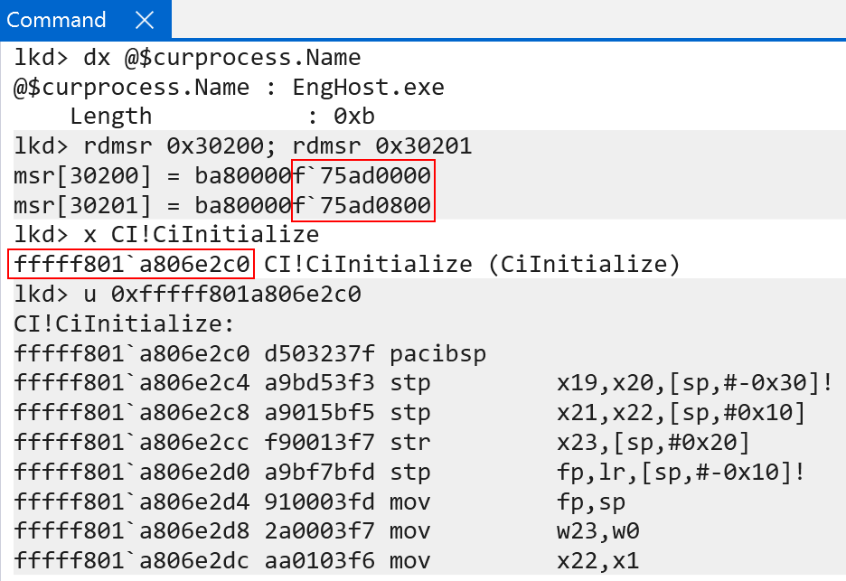
After retrieving the page table root (remember, we are using TTBR1_EL1 in this case because bit 47 is set to 1, which denotes use the kernel page table root) we then:
- Extract bits 46 - 39 (bits 47-63 are simply used to denote the table! Bit 47 is not used in the translation) to retrieve the level 0 page table index
- Index the array (index number + data type size, which is
sizeof(PTE), or 8 bytes)
This gives us the level 0 PTE, which allows us to find the level 1 page table root.
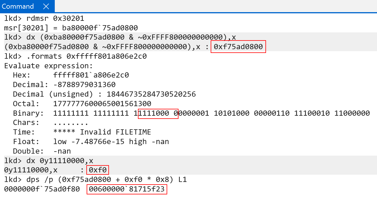
The raw value is 0x0060000081715f23. These are the raw contents of a PTE (represented in software as nt!_MMPTE_HARDWARE). If you are familiar with Windows, you will know the PFN (page frame number) spans bits 47:12 (starting from bit 0). We can simply use bitwise operations to extract the PFN from the PTE, to denote the physical frame. From here, all we then need to do is multiply the PFN by PAGE_SIZE - which is 4KB (based on our granule). This gives us the physical address of the level 1 page table (remember a physical address is simply just a PFN * PAGE_SIZE).
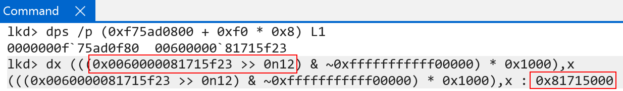
As we just say, bits 46:39 from the target VA are used for the first table index (level 0), and now bits 38:30 are used to index the next table (level 1).
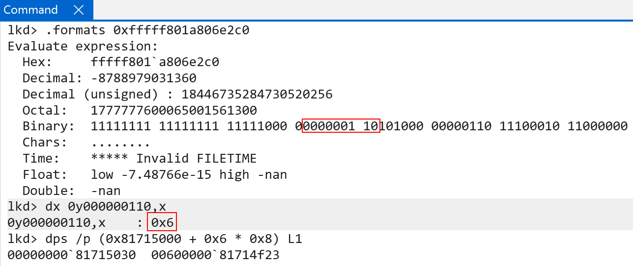
The raw value of this PTE is 0x0060000081714f23 - and this PTE’s PFN describes where the next page table (level 2) lives.
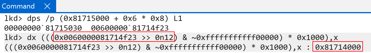
With the base address of the level 2 table, we can simply repeat the process. Bits 29:21in the VA (CI!CiInitialize) are the index used to find the next table - the final level 3 table.
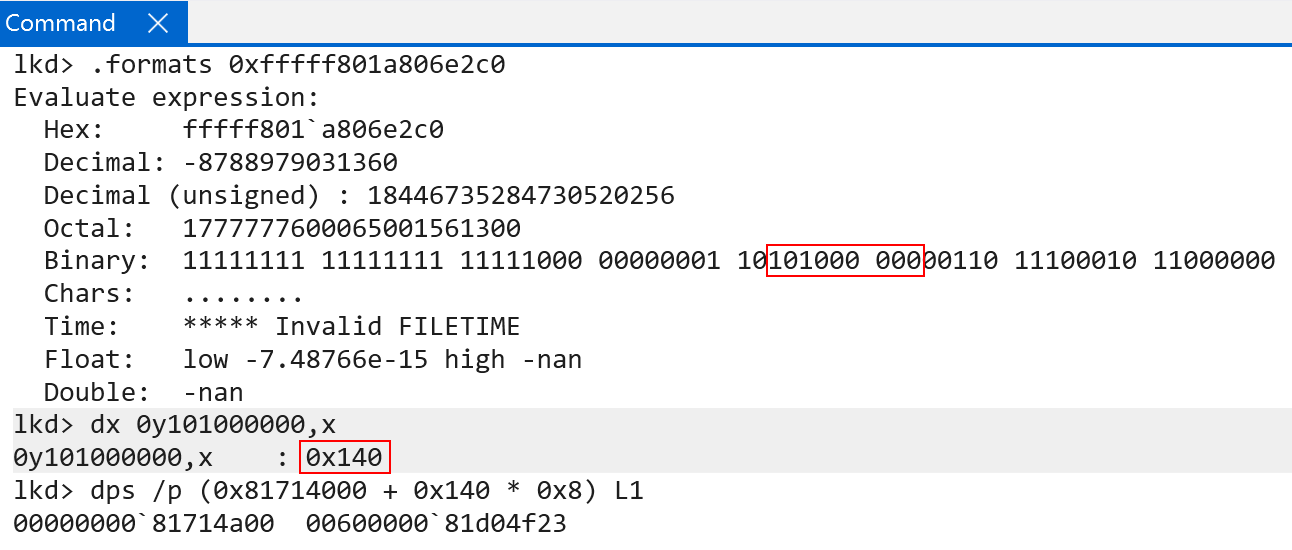
This time the raw PTE value is 0x0060000081d04f23. We now have a PTE that describes the last page table, level 3. We can simply extract the physical page of the level 3 page table and index it one last time to find our final 4KB physical page.
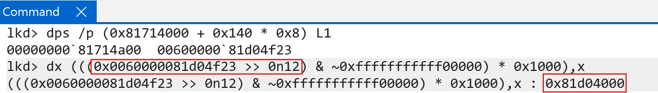
With the physical address, we then can index the level 3 page table using bits 20:12. This will give us the PTE that describes the final physical page (the physical address of CI!CiInitialize).
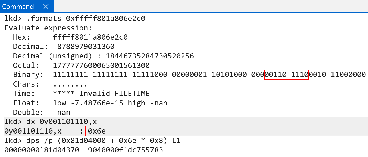
The final PTE’s raw value is 0x9040000fdc755783. Extracting the PFN and calculating the physical address, however, seems a bit off. We get some valid physical memory, which seems to be a function (as it unassembles correctly), but it is not CI!CiInitialize.
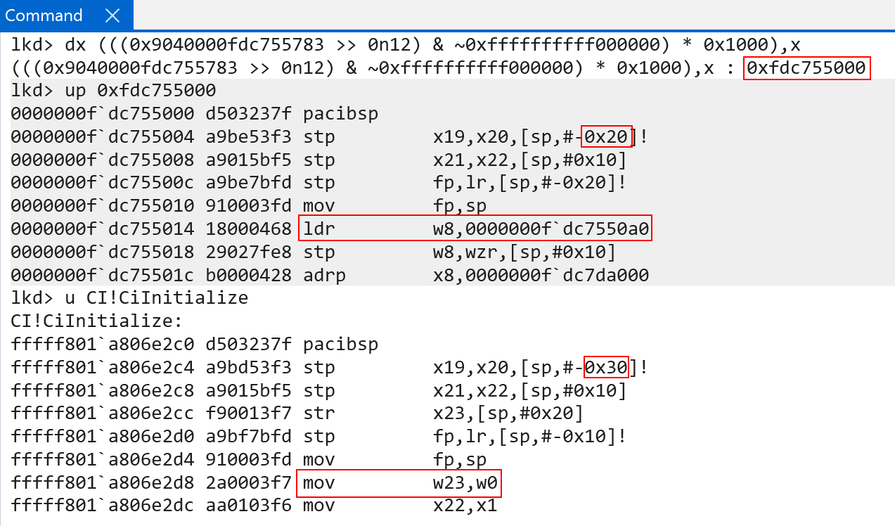
This is because, although bits 20:12 do the last of the page table indexes, bits 11:0 still mean something. Bits 11:0 are meant to be used as an offset into the final translation. What this means, is the physical address produced by the level 3 index (the final block) still needs the remaining bits added on. When we do this, we get the correct physical address of CI!CiInitialize!
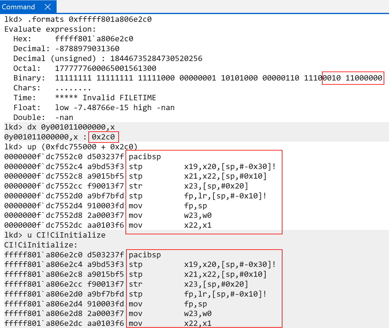
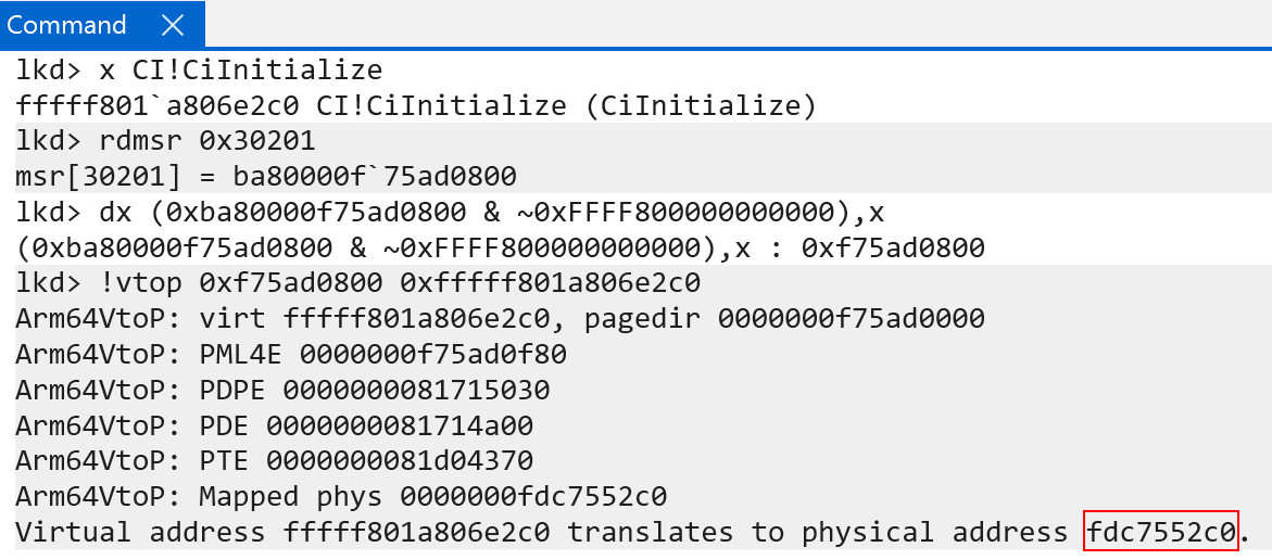
This means the final physical address for CI!CiInitialize is 0xfdc7552c0! We can confirm this with the !vtop extension.
Now, the key obviously here was the leveraging of the PTEs to denote the physical addresses of the paging tables. We have thusfar just referred to PTEs as very “abstract” concepts - with just raw values. Because the PTE layout slightly differs from traditional x86 machines to ARM machines, it is worth talking about the layout of the PTEs on Windows and how also how they are managed.
ARM64 Page Table Entries
Windows under ARM64, identically to x86, leverages the nt!_MMPTE_HARDWARE structure to represent page table entries and uses nt!_MMPFN to describe page frame numbers (PFN). In addition, for reasons we will talk about later, the PTEs are accessible on Windows systems in virtual memory. Recall that in our previous translation analysis we were inspecting physical memory - which contained the PTEs. PTEs reside in physical memory.
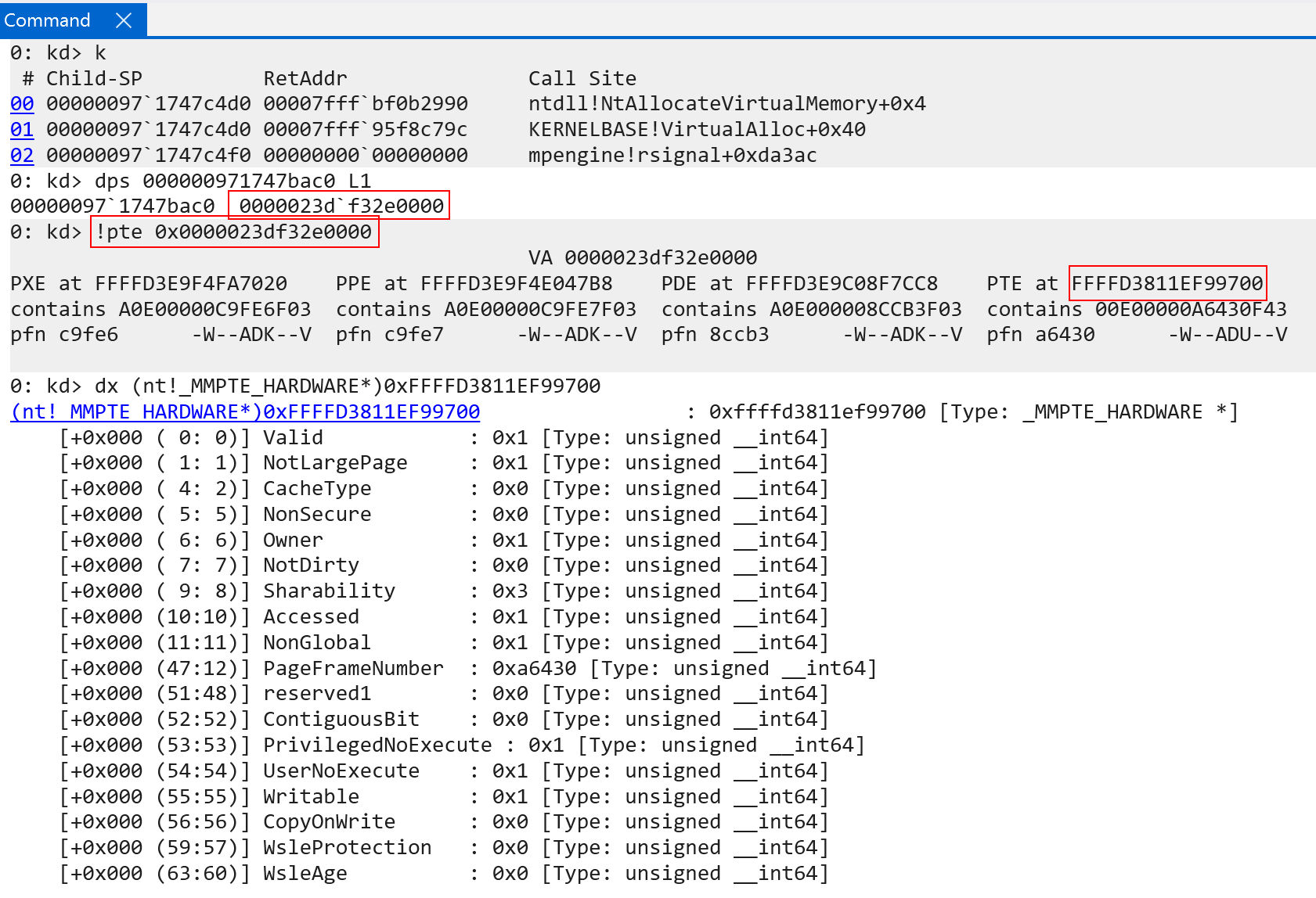
Using WinDbg we can inspect the PTE associated with KUSER_SHARED_DATA in kernel-mode, as well as a user-mode allocation which was allocated via MsMpEng.exe (the Microsoft Defender process).
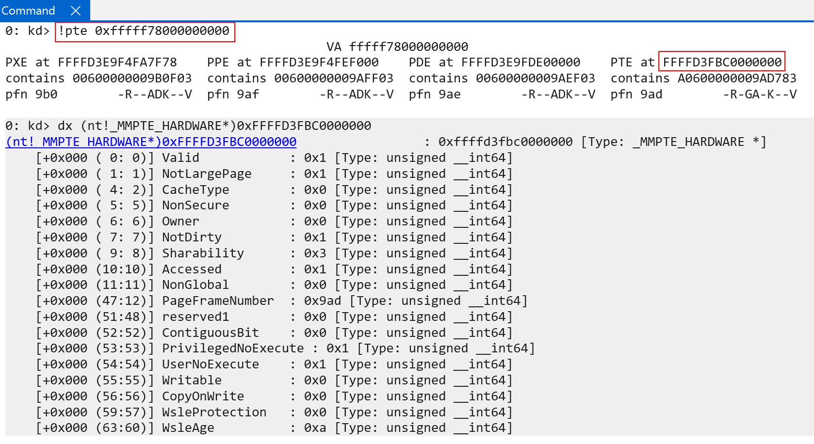
The first thing to call out here is that PXE, PPE, PDE, and PTE are irrelavant here. The appropriate names (level 0 entry, level 1 entry, etc.) have not been updated in the WinDbg !pte extension for ARM.
Additionally, many of the PTE fields will look similar to their x86 counterparts, but there are still a few fields which are worth talking about here:
MMPTE_HARDWARE.NotLargePageMMPTE_HARDWARE.NonSecureMMPTE_HARDWARE.NotDirtyMMPTE_HARDWARE.SharabilityMMPTE_HARDWARE.NonGlobalMMPTE_HARDWARE.PrivilegedNoExecuteMMPTE_HARDWARE.UserNoExecute
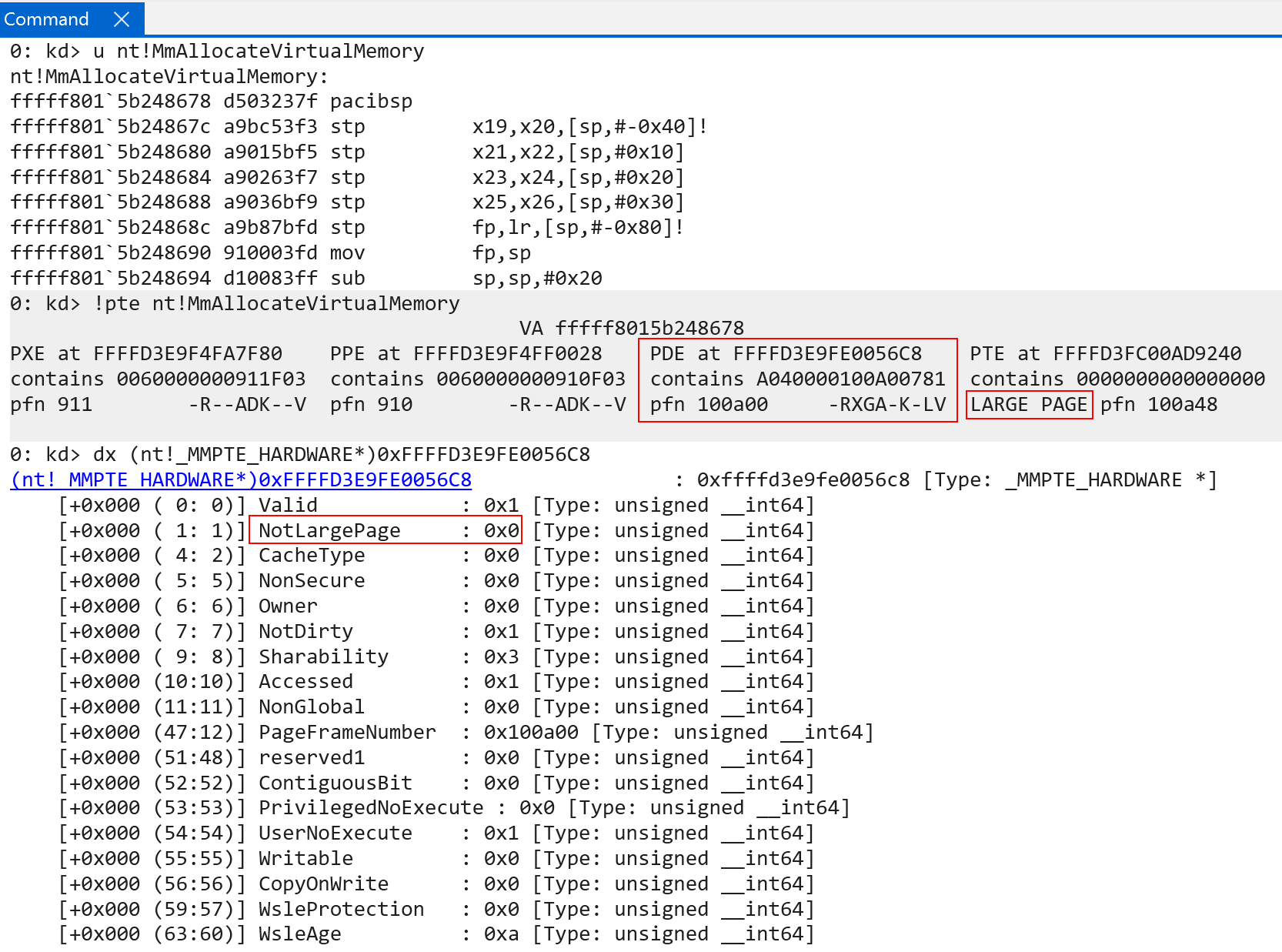
The first, NotLargePage, not not specific to ARM64. “Large pages” are referred to pages which map more memory than the specified granule (4 KB) allows for. This is very common, for instance, for code (usually the .text section but can be other sections) in ntoskrnl.exe. Recall that each page table (level 0, 1, 2) is responsible for addresses a certain amount of memory. As we have already talked about, level 0 addresses 512 GB (512 PTEs, each PTE maps 1 GB of memory). Level 3 addresses 4 KB per PTE. Level 2, which is the table we care about for large PTEs, maps 2 MB of memory per table. This means that a large page is a 2 MB memory mapping, with the final table (level 3) being ignored. Level 2’s PTE becomes the “final” PTE (plus any offset that needs to be added, like we saw with the level 3 table index). NotLargePage is set to 0 to say “this is a large page, ignroe the final PTE”.
The second is NonSecure. We talked briefly earlier about “secure and non-secure states”. The NonSecure bit refers to which security state the in-scope memory belongs to (secure can access secure and non-secure, non-secure can only access itself). As mentioned earlier, Windows does not rely on the security states and, instead, leverages the existing Virtual Trust Levels (VTLs) which have been around since Windows 10 via VBS. However, as ARM documentation states: “In non-secure state, the NS bits [and NSTable bits] in translation tables are ignored.” We have covered this previously - Windows does not “use” the security states and, therefore, although this bit describes the security state, it is ignored on Windows.
The third is NonDirty. This is only worth calling out because on ARM64 this is the inverse of what is present on x64 on Windows. What I mean by this is NonDirty means this page has not been written to, whereas x64 machines maintain a Dirty bit to maintain if a page has been written to.
The fourth is Sharability. This refers to the SH bit by ARM - known as the “shareable attribute”. The behavior for shareability is actually facilitated by TCR_ELX.SHX - where X represents the target exception level. For EL1 on Windows this is typically set to 0b11, or 0x3 - which is why shareability is 3 for both the user-mode and kernel-mode !pte examples we showed earlier. 0x3 corresponds to what is known as “inner shareable” - which is one of three possible states (non-shareable, outer-shareable, and inner-shareable). The shareability of memory comes down to which processors the target memory can be cached on. By setting “inner-shareable” this allows all processors to guarantee cache coherency (all processors can see the same “view” of the caches. Updates to one of the caches are reflected in all caches). There are potentially other use-cases outside the scope of this blog post, especially when it comes to device memory and DMA. the ARM A-Profile documentation section B2.7.1 provides more information.
The fifth is NonGlobal. This is an actual ARM-defined bit referred to as nG. Non-global denotes that the target memory is only valid in context of a specific application. This is why you can see, for example, in our previous user-mode PTE screenshot (memory allocation from MsMpEng.exe) that the user-mode memory has the NonGlobal bit set, while the PTEs that map the kernel-mode memory have NonGlobal set to 0 - as the kernel-mode address space on Windows is shared. Non-global will be talked a bit more about when we get to the TLB.
The sixth and seventh bits are the PrivilegedNoExecute and UserNoExecute bits. These bits are very self-explanatory. The main thing to call out here is the presence of two bits to describe executable permissions - whereas the PTEs on x86-based systems have a single bit with a separate bit denoting if the page is a user or supervisor page. Note that ARM PTEs also still maintain the Owner bit (user/supervisor) on Windows.
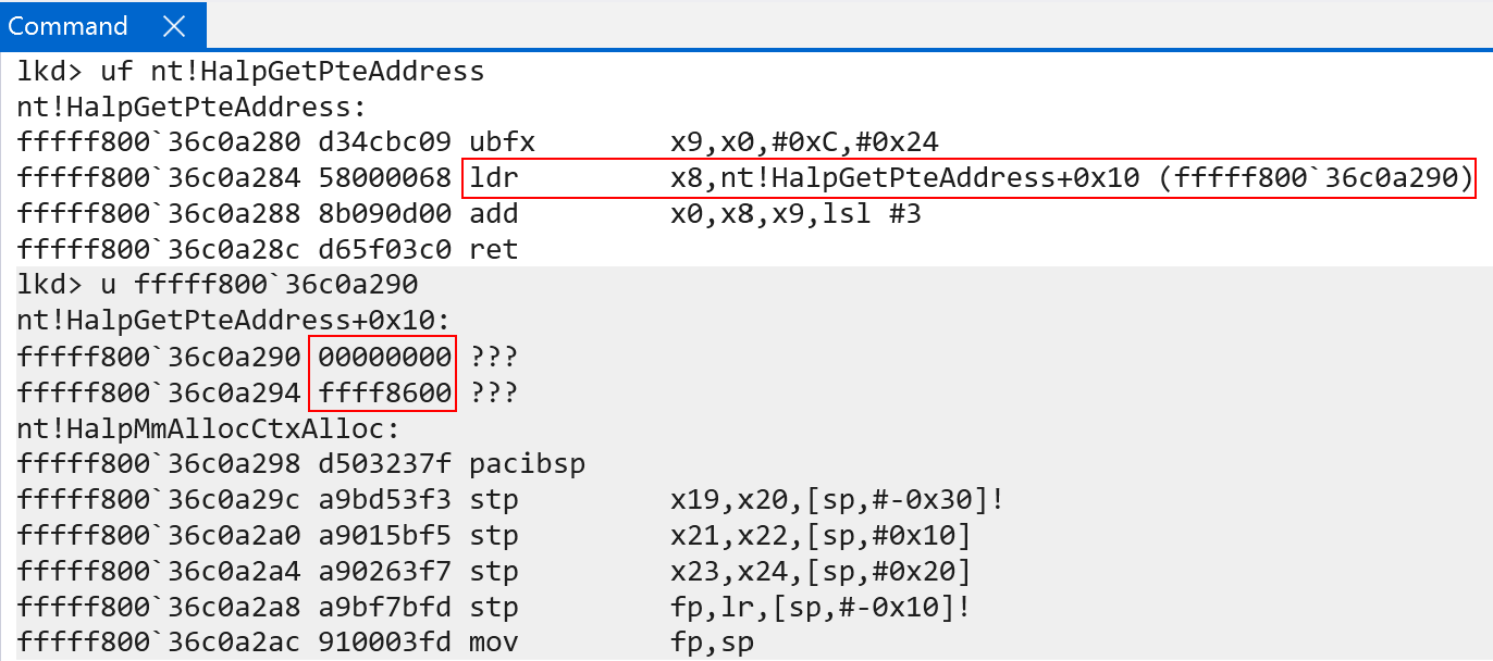
Just like on x86-based installations of Windows, the PTEs are mapped into virtual memory and are randomized on a per-boot basis. My dear friend Alex Ionescu talked about how this works on Windows already. Wrappers like nt!MiGetPteAddress, for dynamic fetching of a particular PTE’s VA, are still present - although the symbol names are different. On ARM, for instance, nt!MiGetPteAddress simply points to nt!HalpGetPteAddress. However, ARM64’s implementation is slightly different based on the mechanics of accessing raw 64-bit values. ARM does not really have the concept of a “direct” loading of an arbitrary 64-bit immediate value (like mov reg, 0x4141414141414141). ARM, instead, has a typical pattern of loading a value from a relative offset. In addition ARM64 typically requires that instruction fetches are aligned to sizeof(WORD) - which refers to 4 bytes in the ARM world. So most code you see is always 4-byte aligned. Why do I bring this up? ARM “uses” “2, 4-byte” slots after nt!HalpGetPteAddress, in-between the PTE function and the next function in the .text section in ntoskrnl.exe as the target for the base of the PTEs. Since ARM effectively “guarantees” that code is 4-byte aligned, typically values that are 64-bit immediates, as an example, are stored at an offset from the instruction they are accessed from. This means that nt!HalpGetPteAddress + 0x10 is the target for the base of the PTEs on ARM. This value is dynamically relocated at runtime.
Lastly, as a point of contention, the process for indexing the PTE array (PTEs in virtual memory) is the same as x64:
- Convert the target address to a virtual page number (VPN) - divide by
sizeof(PAGE_SIZE) - Multiply the
VPN * sizeof(PTE) - Add the base of the PTEs to the value
Although, so far, we have talked about ARM PTEs - one thing that we have not mentioned (although it is already-known throughout the Windows world) is PTE management. The PTEs live in physical memory as we have seen in our previous translation example. However, CPUs can only access virtual memory directly. This leads to an interesting question - how do we manage PTEs from virtual memory (because our CPU requires it) if they live in physical memory? We don’t want to have map and unmap physical memory every single time we want to update a PTE.
Self-Reference Page Tables And Page Table Management
This section of the blog post is not entirely specific to ARM64. However, ARM still does use it on Windows for PTE management in virtual memory (and there are some slight nuances, so probably it is worth talking about anyways) - and I have always felt many of the in-depth explanations of PTE management in virtual memory have left a lot to be desired on Windows systems as many articles assume the reader has knowledge already of these concepts. I also am really passionate about this specific topic because I find the Windows implementation so clever. Since I am already doing a blog post on virtual memory internals, I thought it would be prudent to also talk about how exactly Windows is able to manage the PTEs (in physical memory) from virtual memory at every translation level on ARM (level 0, level 1, level 2, and level 3). On x64 systems you will typically hear the term “Self-Reference PML4 entry”. PML4 refers to the root page table on Intel-based systems. On ARM we can refer to this as “Self-Reference Level 0 entry”.
Recall from a previous section how the translation process works:
Level 0 is used to get level 1’s table address, level 1 is used to get level 2’s table address, level 2 is used to get level 3’s table address, and level 3’s table address is used to get the final page in memory we are looking for (the final physical memory page). Recall how each of these tables is indexed. Each table index results in the fetching of a PTE - which we talked about already. Each PTE provides the page frame number (PFN) - which when multiplied by the size of a page - provides the physical location in memory of the next translation table. This, as we know, is how it breaks down:
- Level 0 table index -> PTE (PTE points to Level 1 entry)
- Level 1 table index -> PTE (PTE points to Level 2 entry)
- Level 2 table index -> PTE (PTE points to Level 3 entry)
- Level 3 table index -> PTE (PTE points to physical memory)
- (Does not result in a table lookup) -> final physical address (extract PFN from previous step, add any offset)
There are 4 table lookups, but the “fifth” step is taking the “final PTE”, extracting the PFN, multiplying by the size of the page (to get the final physical address) and add any relevant offset from the virtual address. We can see this with !vtop:
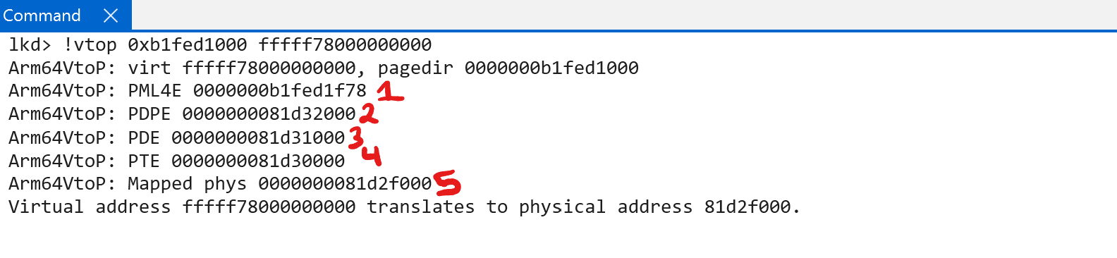
What if, for instance, we “short-circuited” the table lookup and somehow we coherced the processor to only give us three levels of lookup - while maintaing the exact same memory layout? Let’s take a look:
- Level 0 table index -> PTE (PTE points to Level 1 entry)
- Level 1 table index -> PTE (PTE points to Level 2 entry)
- Level 2 table index -> PTE (PTE points to Level 3 entry)
- Level 3 table index -> PTE (PTE points to physical memory)
5. (Does not result in a table lookup) -> final physical address (extract PFN from previous step, add any offset)
Here we can see that the “final” step is no longer the extraction of a physical memory access. Instead, the “last” step is the level 3 table index, meaning the “final” translation here is a PTE instead of a physical address. Specifically the PTE which maps the final physical address is captured. In other words, we get the “PTE” for this page. Let’s take this a step further and short-circuit everything to only “two levels”:
- Level 0 table index -> PTE (PTE points to Level 1 entry)
- Level 1 table index -> PTE (PTE points to Level 2 entry)
- Level 2 table index -> PTE (PTE points to Level 3 entry)
4. Level 3 table index -> PTE (PTE points to physical memory)5. (Does not result in a table lookup) -> final physical address (extract PFN from previous step, add any offset)
The final step now because the PTE which points to the level 3 table PTE. In other words, the “final” result of the translation is the a PTE which on Intel systems we would refer to as the “PDE”. on ARM we can refer to this as the level 2 PTE. We can take this further and keep going “backwards and backwards” until we end up with this:
1. Level 0 table index -> PTE (PTE points to Level 1 entry)
2. Level 1 table index -> PTE (PTE points to Level 2 entry)
3. Level 2 table index -> PTE (PTE points to Level 3 entry)
4. Level 3 table index -> PTE (PTE points to physical memory)
5. (Does not result in a table lookup) -> final physical address (extract PFN from previous step, add any offset)
Theoretically we could go until there are “no” levels used and the level 0 PTE that we started with (the first lookup in the “legitimate” 4-table lookup) is what we end with. This would be paging with “no” or “0” levels.
Now, there are two things to point out here. One is that we have proven that by “short-circuiting” the paging process (e.g., only using 3 of the 4 levels) the “final” address which is translated is that of a page table entry (PTE) - all the way from the PTE that maps the final phyiscal page, to the PTE in the page table root (level 0) which starts the translation process. This, as we can see, provides a mechanism in order to locate the various PTEs in the translation process (whereas normally translation only results in the final physical page).
The second thing to point out here is that it is impossible to ask the processor to “only use” 3 of the 4 levels, as an example, in the translation process. 4 levels will always be used in the current architecture displayed in this blog post (for 64-bit addresses that use “48 bits”). However, we can use a very cool trick in order to actually produce the same result as what we have shown here. By using a self-reference PTE entry it is possible to “simulate” only 3 levels of paging, as an example (on a system where 4 is required), in order to “stop” the translation process one or more levels short. By “stopping” one or more levels short, the “result” of the translation will instead be a PTE instead of a final physical memory address! This is the first step in order to map the PTEs into virtual memory. We will see shortly what we mean by “stopping one or more levels short”.
With the ability to locate, on demand, where any PTE resides (although we have not yet shown what that looks like, just know it is possible at the current moment using the self-reference technique) - the last step would be to simply just map the physical addresses of the PTEs into virtual memory. That is precisely what Windows does - and this is where the self-reference level 0 entry comes into play.
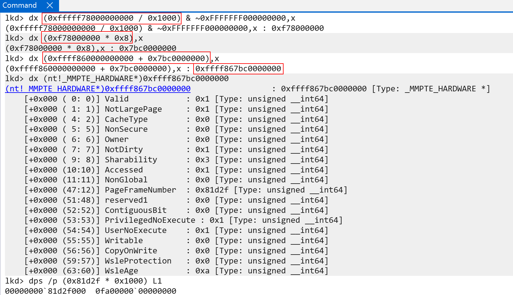
Let us think for one second what we are trying to accomplish. Windows, as we know, maps all of the page tables into virtual memory at a single, flat virtual address which can be indexed as an array. On our machine we know that this array is located at virtual address 0xffff860000000000.
Recall, once more, what a virtual address is. A virtual address is simply a list of indexes into the various page tables (level 0, level 1, etc.) in physical memory. Bits 46:49, 38:30, 29:21, 20:12, and 11:0 of the virtual address are used on Windows. Let’s take our example address of 0xffff860000000000, which is the base of the page tables in virtual memory. Let’s convert this address into the appropriate bit states.
46:39(100001100-> 0xC) -> This is the level 0 table index38:30(000000000-> 0)29:21(000000000-> 0)20:12(000000000-> 0)11:0(000000000-> 0)
Recall that “step 5” is not a table lookup, but physical memory + final offset.
In this case there is only “one valid” index here, and that is the index into the level 0 table. If we use the same translation process as before, we can see that for the “base of the page tables” in virtual memory, the PTE itself simply “points back” to “itself”! This is what is meant by a self-reference PTE! In this case, when the PFN is extracted from the PTE and multiplied by the size of a page, the physical address of “the next page table” -> which should be the address of the level 1 table is instead the address of the level 0 table.
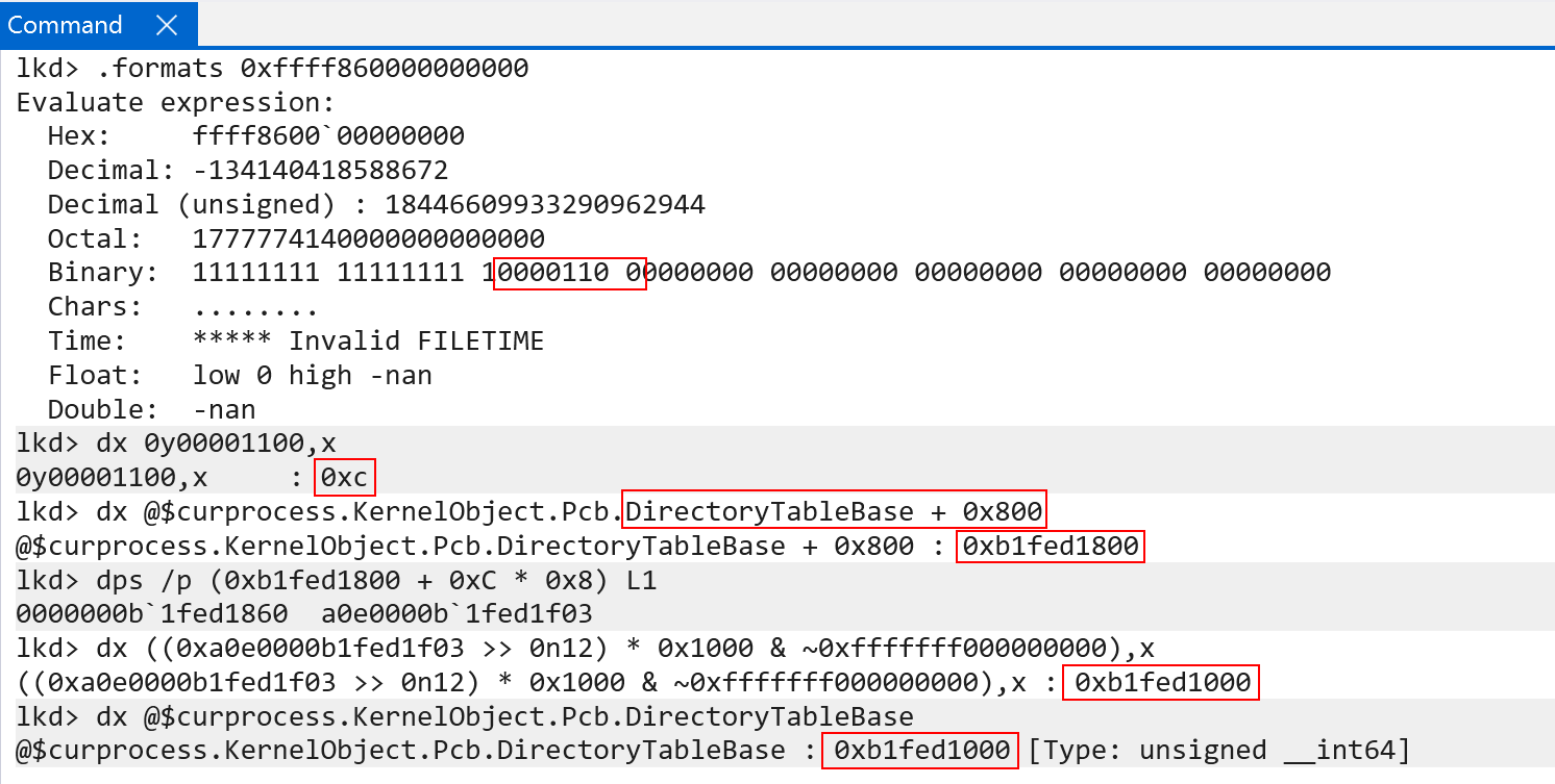
This is exactly how the page tables are mapped into virtual memory. In this case we quite literally have a virtual address that maps to the physical address of the page table root! This is true for each process. In every single page table root (recall each process has their own page table root in KPROCESS.DirectoryTableBase) there is always a special level 0 table index (the self-reference index) that always points “back to itself”. The index is the same throughout all processes. This allows the virtual address 0xffff860000000000 to be used, therefore, to access all page tables for all page tables across all processes (and kernel-mode memory). Again, this is because the address 0xffff860000000000 is setup in such a way that the first index into the first page table, which normally would get us from level 0 to level 1 instead “maps back” to the level 0 table itself - which is the page table root. This gives us a way to access all of the page tables in virtual memory for any process.
Today Windows “randomizes” this self-reference level 0 index. Because this index is randomized (e.g., it could be 0xC on my machine and 0x8 on another machine) this means that the virtual address of the root of the page tables is also randomized (because the VA is constructed from this address). The symbol nt!MmPteBase also contains the root of the page tables in virtual memory. Historically, the PTEs in virtual memory always started at 0xfffff68000000000. This means, as you can guess, the self-reference index was always located at a static index (because the VA was always constructed to this constant value). Alex Ionescu’s post that was linked earlier goes into detail on the randomization process.
Now we have talked about how we map the page tables into virtual memory - but we have not talked about what I have been referring to as “stopping the translation one level short”. Let’s examine this now.
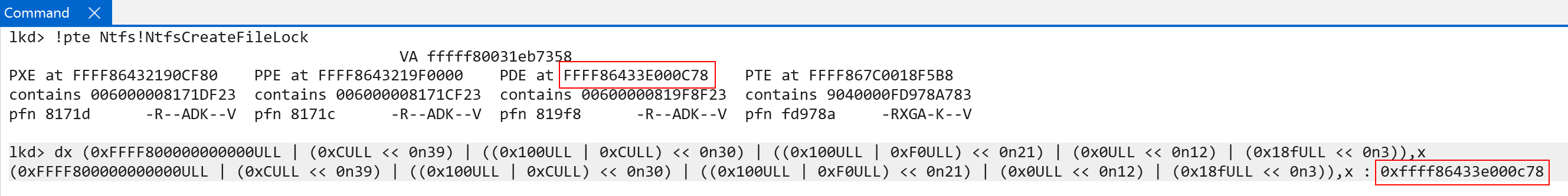
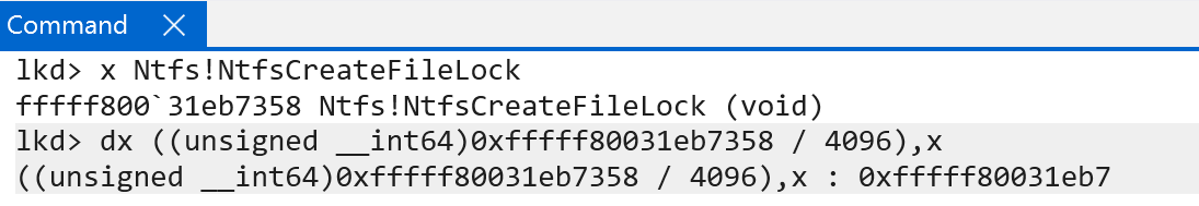
Take, for example, the address of ntfs!NtfsCreateFileLock. On my machine, we can see that the VA is comprised of the following indexes:
- Level 0 ->
0xf0 - Level 1 ->
0x0 - Level 2 ->
0x18f - Level 3 ->
0xb7 - (Final address offset) ->
0x358
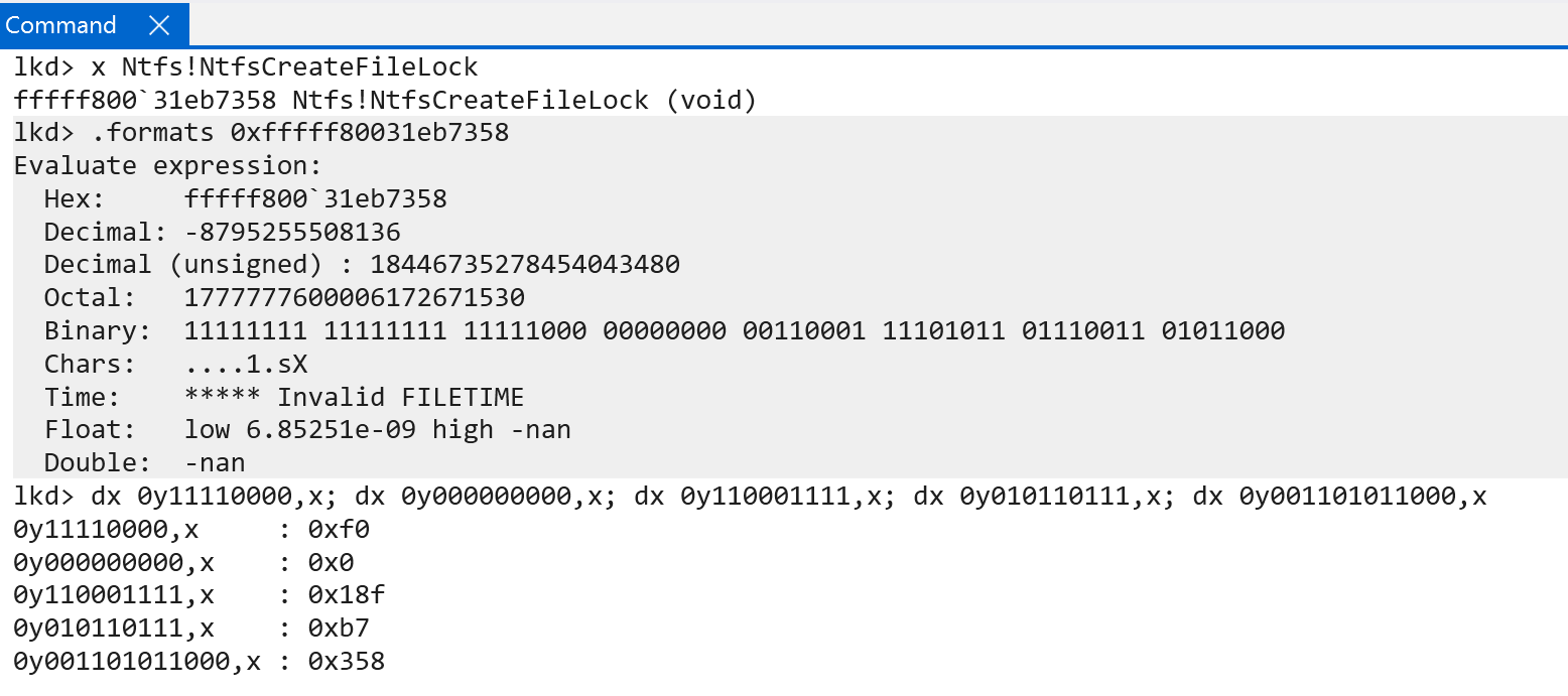
We can prove that these indexes correspond to the appropriate virtual address, as seen below.
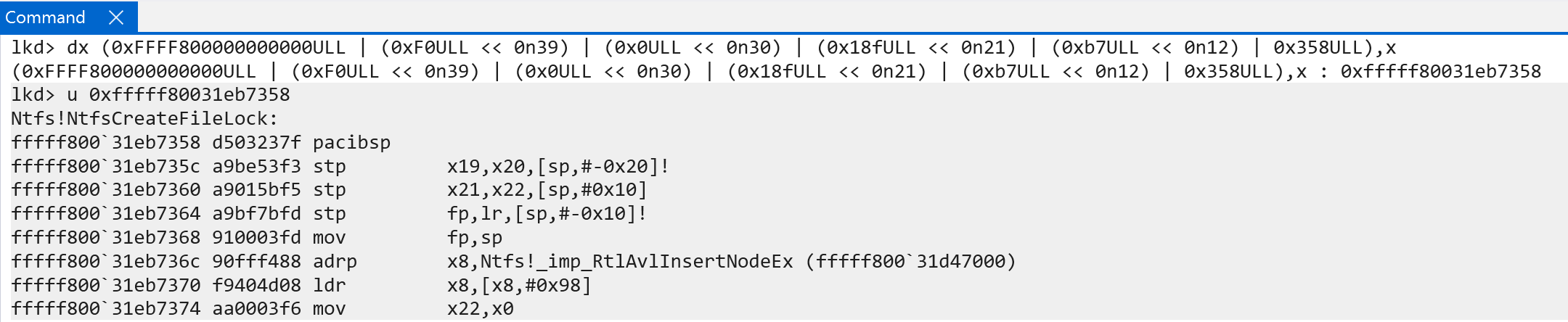
Now, if we wanted to get the PTE (the PTE that maps the final physical memory, so “step 4” from above) - we would need to short-circuit the paging process by one level. This is actually where we use the self-reference entry. We, instead, do the following:
- Level 0 ->
0xf00xC - Level 1 ->
0x00xf0 - Level 2 ->
0x18f0x0 - Level 3 ->
0xb70x18f - (Final address offset) ->
0x3580xb7
Everything in this case is “shifted down” by one level. This give the apperance of “skipping” one level of paging - by stopping the translation right before the final level of translation we previously saw. Here is a diagram outlining this. We know there will always be 4 table lookups and a “final” offset computation step. Knowing this, we can use the self-reference technique to ensure the last “final memory access” now occurs to a PTE, instead of a real 4KB address, because “everything lags behind one level” as we “spent” the first table lookup going back to the level 0 table, instead of indexing the level 1 table.
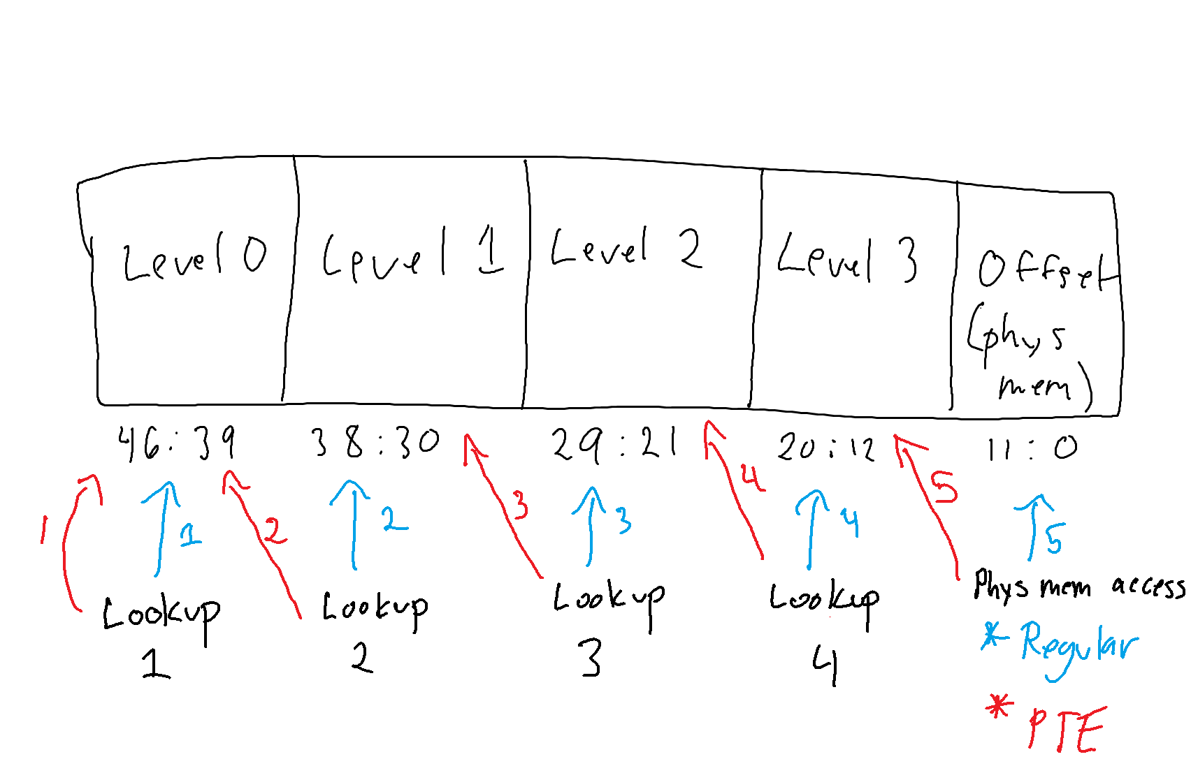
With the self-reference technique, specifically using it to locate the PTE mapping a 4KB page, the last level of translation becomes the original “2nd-to-last” step - which is retrieving the last PTE from the last table walk - meaning the result of the translation is the PTE. This works because of the desired effect of the self-reference. By making the level 0 index “point back to itself” we can effectively “skip” the first level of translation, and everything gets “shifted down by one level”, so-to-speak. Because the level 1 index is now technically indexing a “level 0 table” - because the “result” of where to find the level 1 table actually produces a level 0 table, since again the level 0 index no longer finds a level 1 entry, it finds itself - this means that the level 2 index now indexes a level 1 table, the level 3 index now indexes the level 2 table, and the “final memory access” now “fetches” memory now accesses the “level 3” table instead of the final memory. Again, to reiterate, the translation process effectively “stops” one level too soon - meaning the final access is to a PTE, not to the actual physical memory. This is because the first table lookup causes a “restart” by making level 1 start back over at level 0, but forcing that “one of the 4 lookups” was spent on this restart.
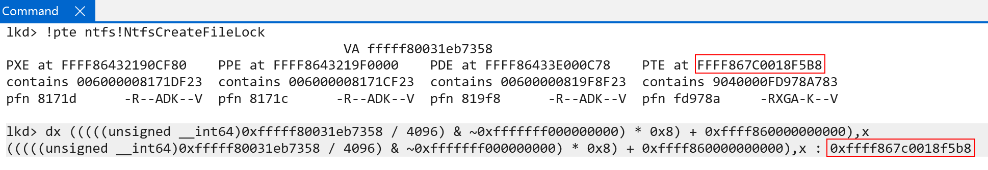
If we “plug these values” into the debugger, we can see that using the indexes we fetched earlier, plus the self-reference entry as the first index, we locate the virtual address of the PTE!
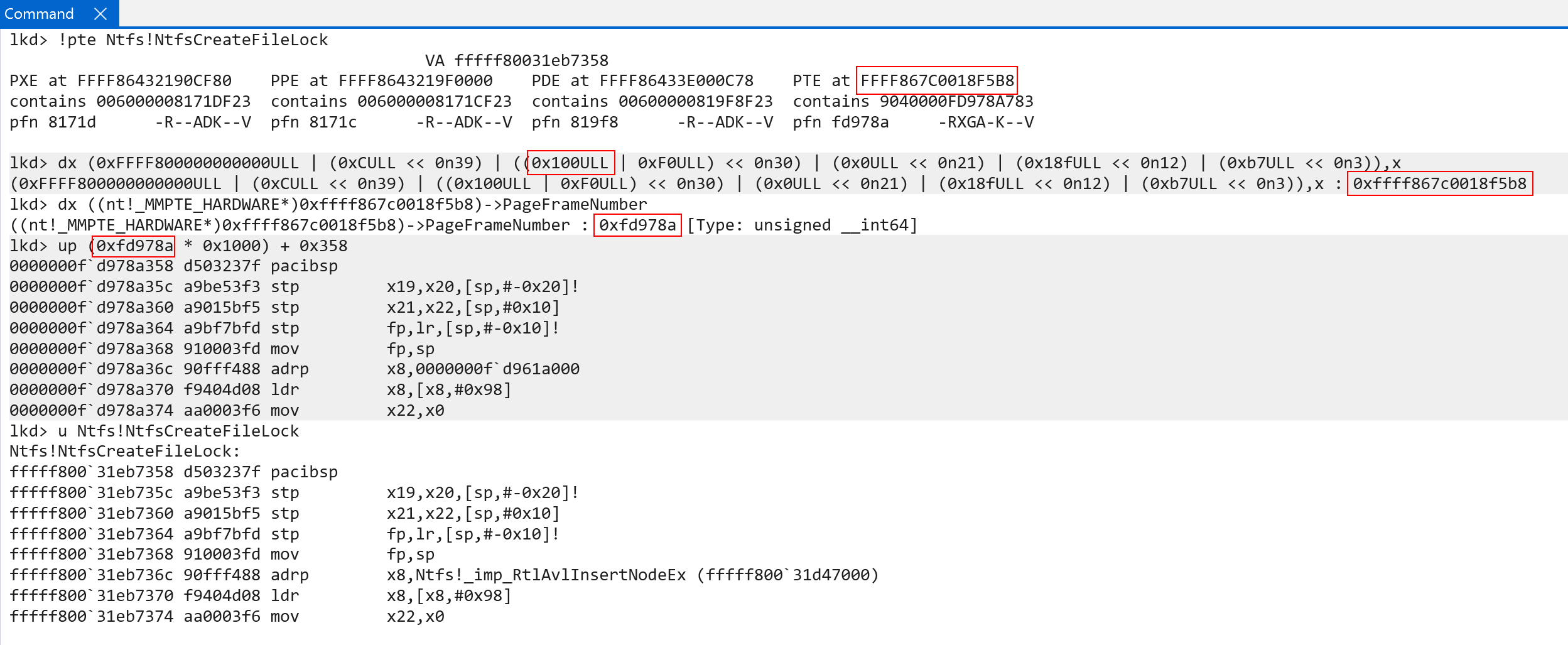
There are two slight nuances that are worth calling out, and why I showed this in the first place.
- Firstly, you can see in the “level 1” index (the second table lookup, with a provided index of
0xF0) we add in the value of0x100. We are trying to translate a kernel-mode address. As we learned earlier, on ARM systems, the page tables are broken out into 2 “halves”. By adding the value of0x100we are instructing our lookup to “use the kernel half” - since this is a kernel-mode address (recall earlier we showed that technically the self-reference entry refers back to the actual root of the page tables, which starts with the user-mode portion. This simply compensates for the fact we are translating a kernel-mode address) - The last and “final” memory lookup does not use bits
11:0, but instead uses bits11:3and leaves2:0set to0. Why is this? The “final memory access” for a true translation (meaning accessing a final 4KB physical page) requires all 12 bits (11:0, because this is the offset into the page where the target memory resides). Here, however, we are not using an offset.0xb7, the final memory access in our PTE-location example, is not an offset into a page of memory - it is instead still an index to a page table. Recall that PTEs are 8 bytes in size. This means that we only use 8 bytes here, and not the full 12 - which is why (11:3are used instead of11:0).
So we now see why the self-reference entry is so important. To “bring it all home” we will show one more example. Instead of another example of PTEs which map physical memory, we will now look at how to extract even “higher level” PTEs in the translation process. Here is what we just did:
- Level 0
- Level 1
- Level 2
- Level 3
<- This is the PTE we just showed how to grab - (Final 4KB page)
Here is what we will do - which is get an even higher level PTE:
- Level 0
- Level 1
- Level 2
<- We will now show how to locate this PTE - Level 3
- (Final 4KB page)
This is a very simple thing, now that we have the fundementals down. We now just need to cause “two short-circuits” of the translation process. To do this we now fill the first two indexes with the self-reference entry. To recap - here is how we found the original address (the 4KB page, the true virtual to physical translation):
- Level 0 ->
0xf0 - Level 1 ->
0x0 - Level 2 ->
0x18f - Level 3 ->
0xb7 - (Final address offset) ->
0x358
Here is how we found the PTE which maps the physical page:
- Level 0 ->
0xf00xC - Level 1 ->
0x00xf0 - Level 2 ->
0x18f0x0 - Level 3 ->
0xb70x18f - (Final address offset) ->
0x3580xb7
Here is how we will now find the PTE which maps the level 3 table. We, once again, “move everything down one level”:
- Level 0 ->
0xC0xC - Level 1 ->
0xf00xC - Level 2 ->
0x00xf0 - Level 3 ->
0x18f0x0 - (Final address offset) ->
0xb70x18f
Because the self-reference entry is now provided twice the final translation will “really be” what was previously the the level 2 table index. Here is what this looks like:
We still have to remember to compensate for the lookup into the “kernel-half” of the page tables, but now we have a primitive to access even higher-level PTEs - all the way back to the very first level (the PTE indexing the level 0 table, which would be synonymous to the PML4E on x86 systems). This gives us a primitive to map all of the page table entries into virtual memory so that they can be managed in software. Additionally, as I have shown in a previous blog using the VA of the page table root (which we say earlier, and is stored in nt!MmPteBase), we incur an O(1) lookup to fetch the PTE in virtual memory for any virtual address on the system by simply indexing the array by the target VA’s “virtual page number”, of VPN. This value can simply be found by dividing the address by the size of a page (4096, or 0x1000), and multiplying the value by the data type size (sizeof(PTE), which is 8 bytes).
There is a very simple reason why this works. It is why we have shown so much analysis so far on translation - recall what a virtual address is. A virtual address is simply a computation of indexes into the various page tables. When we divide the page by 0x1000 we are effectively saying “exclude bits 11:0” from the virtual address. Why is this? Again, bits 11:0 of a virtual address (e.g., like a function in ntoskrnl) are used to compute an offset into the final 4KB page. This is not a table lookup, as we have seen, and is “step 5” in the process (with there being 4 table lookups and one “memory fetch”).
That means the remaining bits (46:12) represent the various indexes into the page tables used for translation. Since we have the root of the page tables (thanks to the self-reference entry, as we saw earlier in nt!MmPteBase’s construction) we just simply add the indexes, provided by bits 46:12, to the base of the PTEs. And, as with any array index, we also have to multiply by the size of the data type. This is a really cool way that Windows manages the PTEs in virtual memory - with such tremendous speeds and performance!
Address Space Identifiers (ASIDs), Virtual Machine Identifiers (VMIDs), and the Translation Lookaside Buffer (TLB)
One of the final things I would like to touch on are some of the differences in behavior of the TLB on ARM64 systems versus a typical x86 machine. The TLB, or translation lookaside buffer, is a caching of memory translations. We know that CPUs only operate on virtual memory - but virtual memory is an operating systems/software construct. Access to virtual memory needs to be translated to the actual physical memory. Now, it would be very unperformant to do 4 table lookups + memory access everytime the CPU needs to access memory (instruction fetches, data, etc.). To combat this, the TLB caches tranlsations. When a CPU goes to access memory, the TLB cache is first checked by the MMU (memory-management unit) of the CPU. If a miss occurs (no cached translation was found), then we fall to the page table walking we have shown in this blog post. There are some differences in TLB behavior that are quite interesting that I think are worth talking about here.
Windows maintains a private per-process address space. This means that, for example, address 0x41414141 may contain the string “Hello” in process A, but in process B 0x41414141 may be invalid, may be reserved but not committed to memory, or may point to some completely different content. This is why historically the TLB was always flushed on context switch. The TLB would only be valid for “the current process” because the addresses for which translations were cached differ between processes. On x86 systems this is typically done by updating the “current” process - by modifying the value in the CR3 control register, which contains “the current page table root”. This is done “under the hood” without an explicit TLB invalidation instruction. It should be noted that the TLB is per-CPU.
There are several items associated with the TLB, but on ARM one of the very interesting things is the present of an “address space” and/or “vitual machine” identifier (ASID/VMID) value. Starting with ASIDs, an ASID is a value that represents, in the TLB, which process the cached translation belongs to. This is not the process ID, but instead a unique value. The reason for this is very interesting in my opinion, and very cool! As I just mentioned, updating the page table root invalidates the TLB so as to not have any “stale” or “false” caches (e.g., process A’s cached translation of 0x41414141 is used instead of process B’s actual 0x41414141). This one of the ways we guarantee the per-process address space on Windows. However, on ARM, swaping page table roots does not automatically invalidate the TLB. This is where the ASID comes into play! The ASID of the “current process” is used to always ensure that any TLB entry accesses correspond to that process! This means, for example, process A could have an ASID of 4 and process B could have one of 8. Both translations for the address 0x41414141 can now be cached in the TLB, because the ASID guarantees that only the correct translation, which corresponds to the target process, is accessed! No more flushing the TLB on every context switch! It should be noted this is specifically talking about non-global (private to a process) pages (whereas global cachings, as long as they are “around”, are already valid in any process).
The ASID namespace is allocated and managed by NT. Support and initialization occurs in nt!KclAsidInitialize.
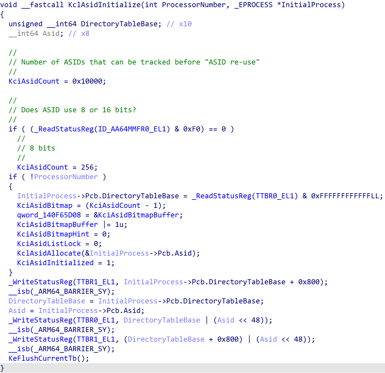
The ID_AA64MMFR0_EL1 system register, specifically the ID_AA64MMFR0_EL1.ASIDBits determines the size of ASID values: either 8 or 16-bits. This is important, because there is some nuance with ASIDs. ASIDs can effectively “wrap” when the last possible value is used. When this occurs, there is TLB invalidation in order to, again, avoid mis-matched TLB translation entries. The larger the ASID value, the more ASIDs the namespace supports, meaning more processes can come-and-go before any wrapping occurs and, thus, TLB flushing. Each process on Windows maintains “it’s” assigned ASID value through it’s KPROCESS object.
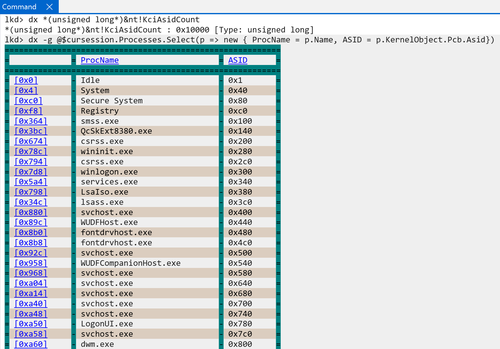
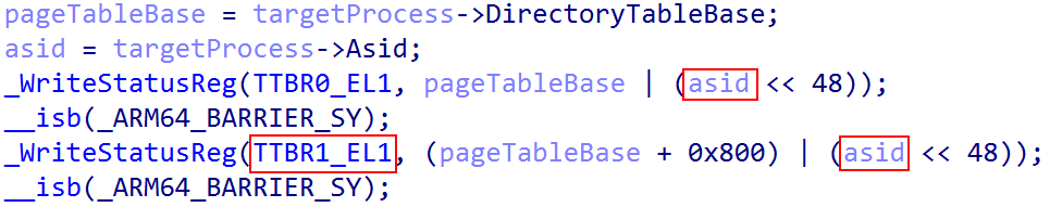
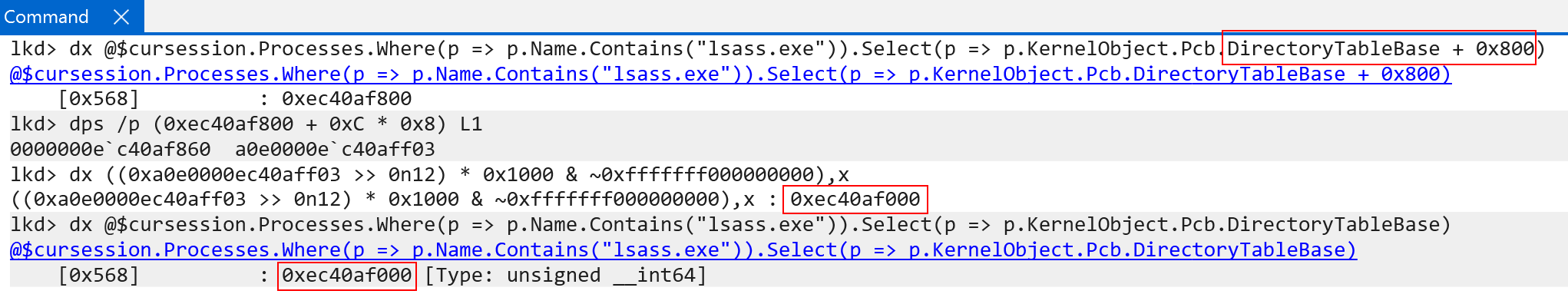
One of the main things to notice is that although we showed KPROCESS.DirectoryTableBase being the “base of the page tables” for a particular process, the actual value in the TTBRX_EL1 system register is the physical address of the root of the page tables alongside the ASID for the target process. This helps us to know what “the current address space” is, and allows the TLB to receive the target ASID when caching translations.
As part of the creation of the process address space on Windows, nt!KclAsidAllocate is called - which assigns an ASID to the target process, and nt!KclAsidFree is called on process deletion.
Although Windows, as we can see in nt!KclAsidInitialize, stores the ASID in each of the two page table root system registers, software still needs to configure which of the page table roots will used by the CPU in order to determine the ASID (we don’t want to use both registers, especially if they are the same. Only one ASID can be in-use at a time). Windows configures configures the TCR_EL1.A1, which specifies that TTBR1_EL1.ASID (the kernel-portion of the page table root), should specify the ASID for the current address space. In addition, it is worth talking about another ARM feature called common not private. This is a bit defined in the root page table system register (TTBRX_EL1.CnP). On Windows, this bit is set to “0” - meaning that translations for the current ASID are allowed to be different from other translations for the same ASID on another processor. As a hypothesis, it would probably make more sense to keep TLBs per-CPU, as this is historically how they have always been treated. This changelog from the Linux kernel actually removes CnP as of 2023 for some of the same reasons as the hypothesis laid out here. This could be wrong, however. I do not work at Microsoft.
Another item of interest, although not applicable to Windows - because VTLs provide the boundary between secure/normal worlds - TLB entries are also marked as secure/non-secure. Similarly to ASIDs - this means that even when switching between security states the TLB does not always have to be invalidated!
In addition to ASIDs, there is another mode of execution that typically occurs on Windows - and that is the hypervisor in EL2. In addition to ASIDs, ARM also provides VMIDs, which are “ASIDs” for VMs. The VMID is used to track which translations in the TLB are associated with which VMs. Again, just like ASIDs, this allows multiple translations to be cached in the TLB at one time since there is a distinction of which VM the translation corresponds to which VM. This, again, allows switching of VMs without needing to always flush the TLB! We should be reminded that this applies to stage 2 translations.
There is a relationship between ASIDs and VMIDs. For instance, we can have a VMID of 5 which has a translation that is cached in the TLB which has an ASID of 6 (VMs “own” their own ASID namespace, just like the EL1 owns one). We then could have a VMID of 10 that also has translation cached in the TLB with an ASID of 6.
There are obviously other nuances not covered here, such as “break-before-make”, covered by FEAT_BBM via ID_AA64MMFR2_EL1.BBM - which has to do with multiple access to TLB entries - one is updating the TLB entry and one is accessing it. These are more-specific to the inner-workings of the MMU, and not necessarily Windows-specific, so we will not cover them here in this section.
Conclusion And Future Work
I have very much been enjoying my new ARM64 Windows machine! I find it more interesting than x86-based machines at this point, and I very much enjoy the architecture. I hope to deliver some more foundational content, such as exception handline and interrupt delivery on ARM64 Windows systems, in the future. Thank you for making it this far into the blog post!
Resources
- Arm Architecture Reference Manual for A-profile architecture: https://developer.arm.com/documentation/ddi0487/latest/
- Arm “Learn the architecture”: https://developer.arm.com/documentation/102142/0100/Virtualization-host-extensions
- To EL2 and Beyond: http://events17.linuxfoundation.org/sites/events/files/slides/To%20EL2%20and%20Beyond_0.pdf
- Arm virtualization paper: https://www.cs.columbia.edu/~nieh/pubs/isca2016_armvirt.pdf
- KVM/arm64 Architectural Evolutions: https://docshare01.docshare.tips/files/26002/260020807.pdf
- Windows Internals, 7th Edition, Part 2
- Some toying with the Self-Reference PML4 Entry: https://blahcat.github.io/2020-06-15-playing-with-self-reference-pml4-entry/